Longitudinal separation adjustable rod guider

A technology of front-to-back distance and guide device, which is applied in the field of guide device, can solve problems such as looseness, small contact area between screws and guide device, and cannot fasten the guide device, so as to increase the contact area, improve work efficiency and economic benefits , the effect of simple structure

Inactive Publication Date: 2012-05-02
HEILONGJIANG JIANLONG IRON & STEEL
View PDF4 Cites 4 Cited by
  • Summary
  • Abstract
  • Description
  • Claims
  • Application Information

AI Technical Summary

Problems solved by technology

[0003] The present invention solves the problem that the screw and the guide of the adjustment device for the front and rear distance of the bar guide have a small contact area and cannot fasten the guide device, and the problem of frequent loosening occurs, and further proposes a bar guide with an adjustable front and rear distance device

Method used


Image

  • Longitudinal separation adjustable rod guider
  • Longitudinal separation adjustable rod guider
  • Longitudinal separation adjustable rod guider

Examples


specific Embodiment approach 1

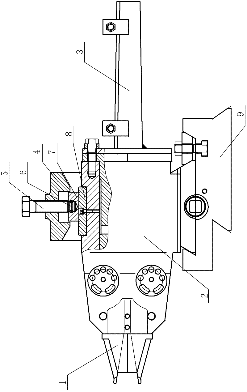
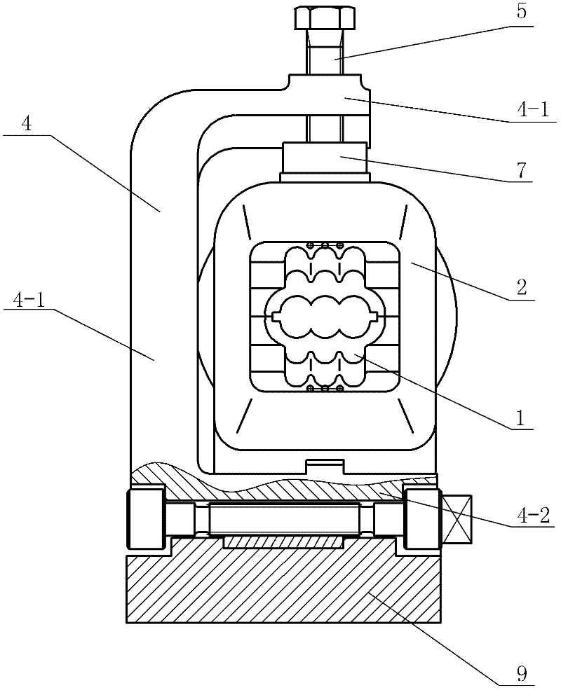
[0007] Specific implementation mode one: combine figure 1 , figure 2 and image 3 Describe this embodiment, a front-rear distance-adjustable rod guide device described in this embodiment includes a nose cone 1, a guide assembly 2, a guide groove 3, a bracket assembly 4, a compression screw 5, an elastic cylindrical pin 6, an upper Tooth block 7 and lower tooth block 8, described bracket assembly 4 is made up of upper crossbeam 4-1, lower crossbeam 4-2 and vertical plate 4-3, described upper crossbeam 4-1, lower crossbeam 4-2 are respectively connected with vertical The upper end and the lower end of the plate 4-3 are fixed into one body, and the upper beam 4-1 and the lower beam 4-2 are arranged side by side in parallel on one side of the vertical plate 4-3, and the guide assembly 2 is installed on the lower beam 4-2 On the upper surface of the upper surface, the nose cone 1 is connected to one end of the guide assembly 2, the guide groove 3 is connected to the other end of...

specific Embodiment approach 2

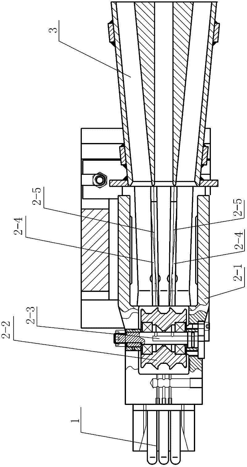
[0008] Specific implementation mode two: combination figure 1 This embodiment is described. The guide assembly 2 of a front-rear distance-adjustable bar guide device in this embodiment includes a box body 2-1, two dividing wheels 2-2, two eccentric shafts 2-3, Two tool holders 2-4 and two blades 2-5, two eccentric shafts 2-3 are inserted side by side and parallel in one end of the box body 2-1 from top to bottom, and each cutting wheel 2-2 is set separately On an eccentric shaft 2-3, two knife rests 2-4 are installed side by side in parallel in the other end of the box body 2-1 along the length direction of the box body 2-1, and the two knife rests 2-4 are on the same horizontal plane Inside, a blade 2-5 is respectively installed on each knife holder 2-4. Other components and connections are the same as those in the first embodiment.

specific Embodiment approach 3

[0009] Specific implementation mode three: combination figure 1 , figure 2 and image 3 To illustrate this embodiment, the front-rear distance-adjustable bar guide device in this embodiment further includes a base 9 on which the bracket assembly 4 is installed. Other compositions and connections are the same as those in Embodiment 1 or 2.

[0010] working principle

[0011] When the present invention is used, the box body 2-1 is installed on the lower crossbeam 4-2, after adjusting the position of the box body 2-1, the upper tooth block 7 is pushed down by the compression screw 5 until the upper tooth block 7 and the lower tooth block 7 The tooth blocks 8 are firmly meshed, and the workpiece is sent into the guide assembly 2 for cutting; after the work is completed, the upper tooth block 7 is pulled by the compression screw 5 to move upward until the upper tooth block 7 and the lower tooth block 8 are separated.


PUM


Abstract

A longitudinal separation adjustable rod guider is disclosed, and relates to a guider, in particular to a longitudinal separation adjustable rod guider. The invention solves the problems that the contact area of the screw and guiding of an adjustor of the longitudinal separation before guiding the bar is small so as not able to fasten the guider and the guider is loosened always. The longitudinal separation adjustable rod guider comprises a nose cone, a guiding assembly, a guide slot, a bracket assembly, a compressing screw, an elastic cylindrical pin, an upper tooth piece and a lower tooth piece. The bracket assembly consists of an upper beam, a lower beam and a vertical plate. The upper and lower beams are respectively connected fixedly with the upper and lower ends of the vertical plate as a whole. The guiding assembly is installed on the upper surface of the lower beam. The nose cone is connected with one end of the guiding assembly while the other end of the guiding assembly is connected with the guide slot. The lower tooth piece is installed on the upper surface of the guiding assembly, the compressing screw penetrates through the upper beam up and down and the upper tooth piece is connected with the lower end of the compressing screw through the elastic cylindrical pin. The invention is used to ensure that the rolled pieces move along a correct in-and-out roller.

Description

technical field [0001] The invention relates to a guide device, in particular to a bar guide device with front and rear distance adjustment. Background technique [0002] The bar guide is an important equipment in metallurgical rolling. Usually, the distance between the guide and the roll is adjusted according to the diameter of the roll to meet the needs of the process. At present, the front and rear distance adjustment method commonly used by the bar guide is the screw compression method. , because the contact surface between the screw and the guide is small, it is difficult to generate enough friction to fasten the guide, and the screw will loosen due to the vibration generated by the bar guide often being hit by the rolled piece, which has caused safety problems in production. Hidden danger. Contents of the invention [0003] The present invention solves the problem that the screw and the guide of the adjustment device for the front and rear distance of the bar guide ...

Claims


Application Information

Patent Timeline
Patent Type & Authority Applications(China)
IPC IPC(8): B21B39/16
Inventor 翟长宏姚本金
Owner HEILONGJIANG JIANLONG IRON & STEEL
Why Eureka
Try Eureka