

Viscoelasticity measuring apparatus
A measuring device and viscoelastic technology, applied in the direction of measuring device, measuring force, diagnostic recording/measurement, etc., can solve problems such as measurement that is not suitable for handling small pressure and high precision, and achieves alleviating the influence of jitter, reducing power consumption, reducing The effect of dithering
- Summary
- Abstract
- Description
- Claims
- Application Information
AI Technical Summary
Problems solved by technology
Method used
Image

Examples
no. 1 approach
[0072] Hereinafter, a first embodiment of the present invention will be described with reference to the drawings and the like.
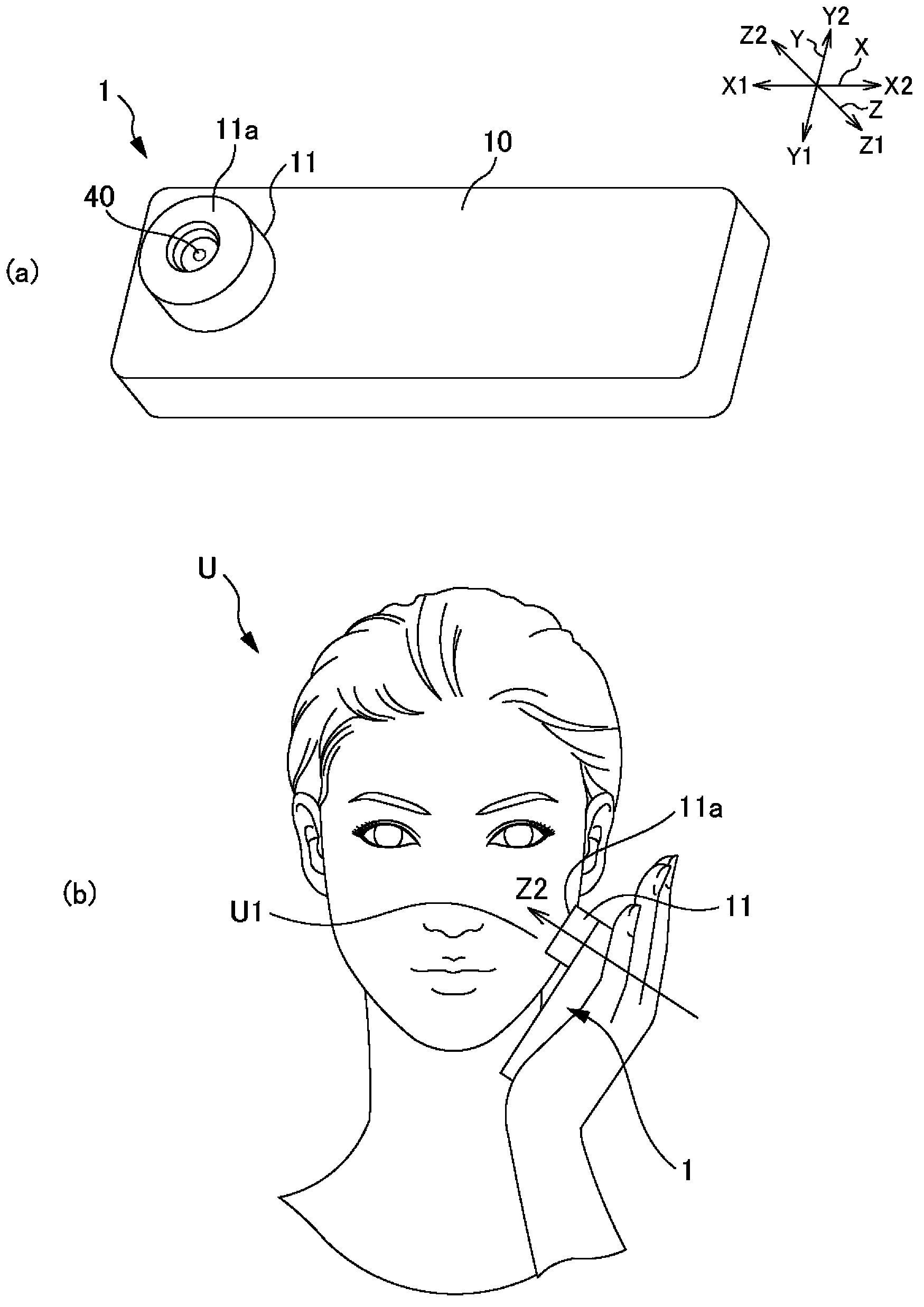
[0073] figure 1 It is a figure which shows the perspective view of the measuring apparatus 1 of 1st Embodiment, and a usage form.
[0074] figure 1 (a) is a perspective view of the measuring device 1 .
[0075] figure 1 (b) is a diagram showing how the measurement device 1 is used.
[0076] In addition, in the description of the embodiment and the drawings, the figure 1 The state of (b) is based on the left-right direction X, the depth direction Y, and the thickness direction Z.
[0077] The measurement device 1 is a rectangular parallelepiped that is long and thin in the left-right direction X. The size of the measuring device 1 is a size that can be accommodated in a palm. The measuring device 1 is a viscoelasticity measuring device that presses a ball indenter 40 into the skin U1 to measure the viscoelasticity of the skin U1.
[0078] ...
no. 2 approach
[0161] Next, a second embodiment of the present invention will be described.
[0162] In addition, in the description and drawings of each of the following embodiments, the same reference numerals are attached to the parts that realize the same functions as those of the above-mentioned first embodiment, or the same reference numerals are attached to the end (the last two digits), as appropriate. Duplicate descriptions are omitted.
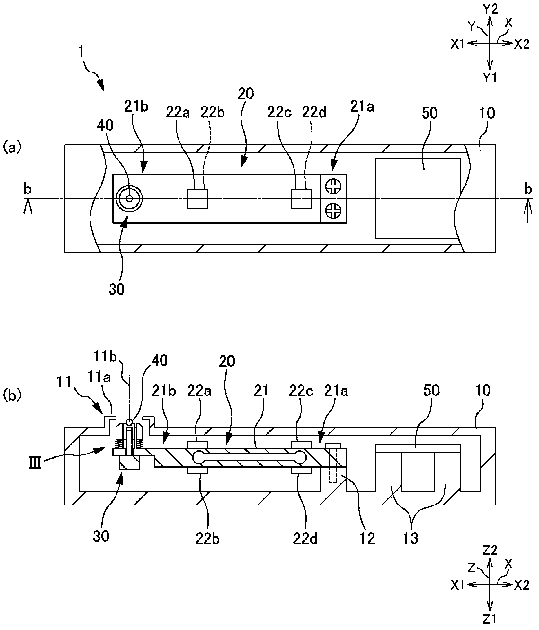
[0163] Figure 6 It is a plan view and a cross-sectional view of the measurement device 201 of the second embodiment (equivalent to figure 2 diagram).
[0164] The measurement device 201 includes a load cell 220 and a base 225 .
[0165] The load sensor 220 uses a small piezoelectric element such as a cylindrical shape. The lower surface (fixed end side) of the load sensor 220 is fixed to the bottom surface of the housing 210 . A base 225 is fixed to the upper surface (movable end side) of the load cell 220 .
[0166] The base 225 serves as ...
no. 3 approach
[0170] Next, a third embodiment of the present invention will be described.
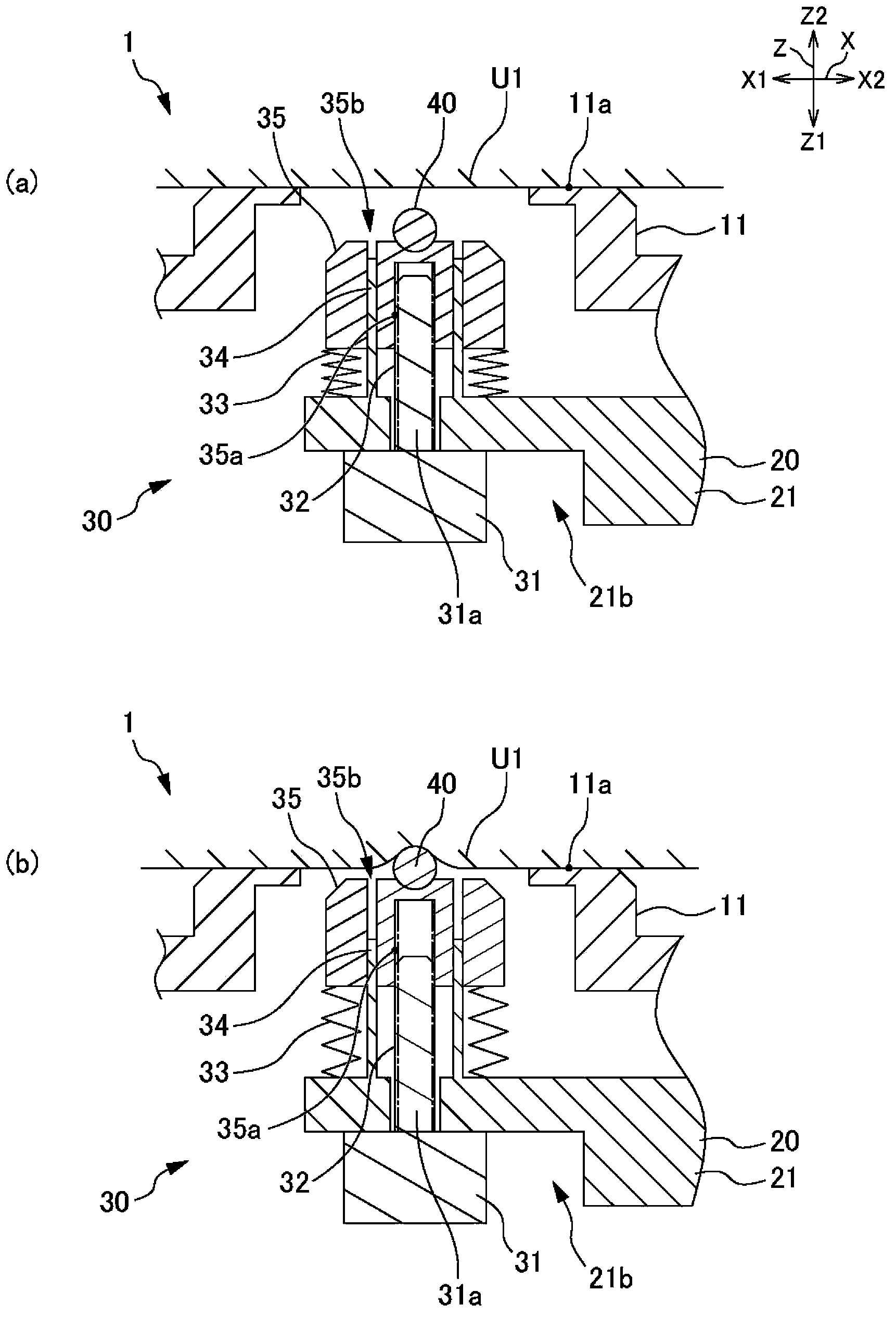
[0171] Figure 7 It is a perspective view of measuring devices 301-1 to 301-3 of the third embodiment.
[0172] Such as Figure 7 As shown in (a), the measurement device 301 - 1 includes an adhesive sheet 371 .
[0173] The adhesive sheet 371 is disposed on the front end of the annular portion 11 . The adhesive sheet 371 adheres to the skin at the time of measurement. Thus, the measurement device 301-1 can correct the contact angle between the ball indenter 40 and the skin surface, and even when the measurer shakes or moves, the front end (surface contact part) of the annular part 11 can be brought into contact with the skin. The surface is tightly bonded to reduce the influence of vibration on the measurement.
[0174] Such as Figure 7 As shown in (b), the measurement device 301 - 2 includes three pressure sensors 372 .
[0175] The pressure sensors 372 are arranged at equal intervals at the...
PUM
 Abstract
Description
Claims
Application Information