Mandrel cooling device

A technology for cooling equipment and mandrels, applied in metal processing equipment, metal rolling, manufacturing tools, etc., can solve problems such as poor economy, affecting product quality, production accidents, etc., achieve high economy and market prospects, uniform and fast cooling , Improve the effect of production quality

Inactive Publication Date: 2014-02-12
TAIYUAN HEAVY IND
View PDF6 Cites 15 Cited by
  • Summary
  • Abstract
  • Description
  • Claims
  • Application Information

AI Technical Summary

Problems solved by technology

[0002] In the production of seamless steel pipes, the mandrel penetrates into the capillary and cooperates with the rolling machine to reduce the wall thickness of the heated capillary to form a waste pipe. During the rolling process, the appearance of the mandrel and the capillary will generate more than 900°C For the rolling equipment that uses a single mandrel for rolling tubes, the mandrel needs to be cooled to about 90°C and then sprayed with lubricant on the outer surface before the next tube rolling. If the mandrel is not cooled properly, the lubricant cannot be applied However, rolling the pipe will cause quality defects and even production accidents in the waste pipe.
[0003] The existing mandrel cooling method is generally cooling by circulating water inside the mandrel, but this method will increase the production cos...

Method used


Image

  • Mandrel cooling device
  • Mandrel cooling device
  • Mandrel cooling device

Examples


Embodiment Construction

[0022] Typical embodiments embodying the features and advantages of the present invention will be described in detail in the following description. It should be understood that the present invention is capable of various changes in different embodiments without departing from the scope of the present invention, and that the description and drawings therein are illustrative in nature and not limiting. this invention.

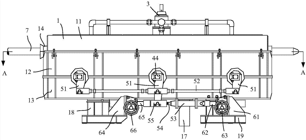
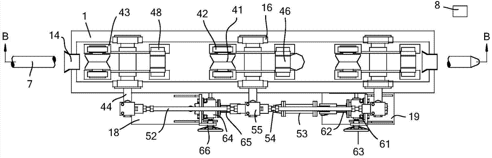
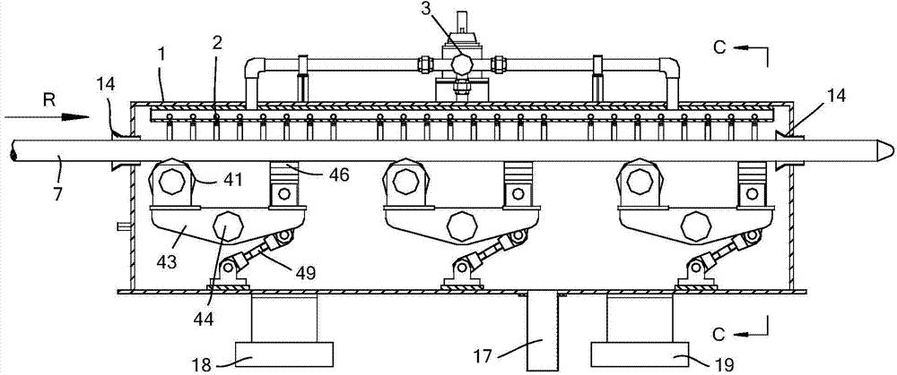
[0023] Such as figure 1 , figure 2 , image 3 with Figure 4 As shown, the mandrel cooling equipment of the present invention includes a box body 1, a spray ring 2, a waterway control system 3, multiple sets of supporting rollers, an adjustment mechanism, a positioning mechanism and a fine-tuning mechanism. In the present invention, the mandrel 7 is transported by multiple sets of supporting rollers, and the mandrel 7 is cooled by the spray ring 2 during the transport process.

[0024] Such as figure 1 , figure 2 with image 3 As shown, the box body 1 i...


PUM


Abstract

The invention discloses a mandrel cooling device which comprises a box body, multiple groups of support rollers and multiple groups of sprinkling rings, wherein the bottom of the box body is fixed through a support, and water sealing curtains are arranged at ports at two ends of the box body; the multiple groups of support rollers are mounted in the box body and uniformly and linearly arranged in the walking direction of the mandrel in sequence, each support roller in the multiple groups of support rollers comprises a V-shaped roller, a V-shaped support groove, a shoulder pole beam, a rotating shaft and an adjusting mechanism, a rotation center of the shoulder pole beam is fixedly connected with the rotating shaft which is mounted on the box body in a pivot manner and fixedly connected with the adjusting mechanism, the adjusting mechanism is arranged outside the box body, the V-shaped roller and the V-shaped support groove are formed in two ends of the shoulder pole beam respectively, the V-shaped roller comprises two rollers which are oppositely arranged in a V-shaped manner, and the V-shaped support groove is made of soft wear-resisting metal; and multiple groups of sprinkling rings are arranged in the box body, located above the multiple groups of support rollers and communicated with a water way, and further, the sprinkling directions face the mandrel. The mandrel cooling device is applied to a rolled pipe production line, the application range is broad, and the mandrel cooling is uniform and fast.

Description

technical field [0001] The invention relates to a pipe rolling machine, in particular to equipment for cooling a pipe rolling mandrel rod in the production of seamless steel pipes. Background technique [0002] In the production of seamless steel pipes, the mandrel penetrates into the capillary and cooperates with the rolling machine to reduce the wall thickness of the heated capillary to form a waste pipe. During the rolling process, the appearance of the mandrel and the capillary will generate more than 900°C For the rolling equipment that uses a single mandrel for rolling tubes, the mandrel needs to be cooled to about 90°C and then sprayed with lubricant on the outer surface before the next tube rolling. If the mandrel is not cooled properly, the lubricant will not be applied And rolling the pipe will cause quality defects and even production accidents in the waste pipe. [0003] The existing mandrel cooling method is generally cooling by circulating water inside the man...

Claims


Application Information

Patent Timeline
IPC IPC(8): B21B25/04
Inventor 张良夫秦臻王爱国
Owner TAIYUAN HEAVY IND
Why Eureka
Try Eureka