Helical blade forming device

A technology for forming and processing helical blades, which is applied in the field of forming and processing devices for helical blades, can solve problems such as poor precision and low production efficiency, and achieve the effects of shortening process time, high processing precision and improving work efficiency.

Inactive Publication Date: 2014-02-12
HUANGSHI ZHIYUN ELECTROMECHANICAL TECH INST
View PDF0 Cites 2 Cited by
  • Summary
  • Abstract
  • Description
  • Claims
  • Application Information

AI Technical Summary

Problems solved by technology

[0002] At present, when processing spiral blades, first process a plurality of rings, and then saw a slit along the radial direction of each ring, and then heat the other side of the ring directly opposite to the slit, and then use two Workers each use a pair of pliers to place on the two sides of the seam on the ring, and break them apart in the opposite direction to a suitable position. This processing method has poor precision and extremely low production efficiency.

Method used


Image

  • Helical blade forming device
  • Helical blade forming device

Examples


Embodiment Construction

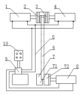
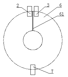
[0008] see Figure 1 to Figure 2 , the present invention comprises a left hydraulic cylinder 1, a left chuck 2, a right chuck 3, a right hydraulic cylinder 4, a lower chuck 7, a lower hydraulic cylinder 8, a hydraulic station 9 and an electric control box 10, and the lower chuck 7 includes Fixed clip 71 and movable clip 72, described left chuck 2 is connected with the extension shaft of left hydraulic cylinder 1, and described right chuck 3 is connected with the extension shaft of right hydraulic cylinder 4, and described movable clip The block 72 is connected with the extension shaft of the lower hydraulic cylinder 8, and the hydraulic station 9 is respectively connected with the left hydraulic cylinder 1, the right hydraulic cylinder 4 and the lower hydraulic cylinder 8 through the oil pipe 5 to form a hydraulic control circuit, and the electric control box 10 It is connected with the hydraulic station 9 by wires to form an electrical control circuit.

[0009] During work, ...


PUM


Abstract

The invention discloses a helical blade forming device, which comprises a left hydraulic cylinder (1), a left chuck (2), a right chuck (3), a right hydraulic cylinder (4), a lower chuck (7), a lower hydraulic cylinder (8), a hydraulic station (9) and an electric cabinet (10). The lower chuck (7) comprises a fixed fixture block (71) and a movable fixture block (72); the left chuck (2) is connected with a projecting shaft of the left hydraulic cylinder (1); the right chuck (3) is connected with a projecting shaft of the right hydraulic cylinder (4); the movable fixture block (72) is connected with a projecting shaft of the lower hydraulic cylinder (8); the hydraulic station (9) is respectively connected with the left hydraulic cylinder (1), the right hydraulic cylinder (4) and the lower hydraulic cylinder (8) by an oil pipe (5) to form a hydraulic control loop; the electric cabinet (10) is connected with the hydraulic station (9) by a lead to form an electric control loop. The helical blade forming device disclosed by the invention is simple in operation, safe and reliable, high in processing precision and capable of remarkably improving the work efficiency.

Description

technical field [0001] The invention relates to a spiral blade processing machine, in particular to a spiral blade forming processing device. Background technique [0002] At present, when processing spiral blades, first process a plurality of rings, and then saw a slit along the radial direction of each ring, and then heat the other side of the ring directly opposite to the slit, and then use two Workers each place a pair of pliers on the two sides of the seam on the ring, and break it apart to a suitable position along the opposite direction. This processing method has poor precision and extremely low production efficiency. Contents of the invention [0003] The purpose of the present invention is to provide a spiral blade forming processing device which is simple in operation, safe and reliable, high in processing precision and can significantly improve work efficiency. [0004] To achieve the above object, the present invention includes a left hydraulic cylinder, a le...

Claims


Application Information

Patent Timeline
IPC IPC(8): B21D31/00
Inventor 黄凌志
Owner HUANGSHI ZHIYUN ELECTROMECHANICAL TECH INST
Why Eureka
Try Eureka