
Oil baffle plate and compressor applying oil baffle plate

An oil baffle, oil and gas technology, which is applied to the parts of pumping devices for elastic fluids, mechanical equipment, machines/engines, etc., can solve the problems of large amount of refrigeration oil and adverse effects on the performance of air conditioning systems, etc.

Inactive Publication Date: 2014-02-12
ZHUHAI GREE REFRIGERATION TECH CENT OF ENERGY SAVING & ENVIRONMENTAL PROTECTION
View PDF9 Cites 4 Cited by
  • Summary
  • Abstract
  • Description
  • Claims
  • Application Information

AI Technical Summary

Problems solved by technology

However, the above-mentioned oil baffle plate cannot well block the mixture of refrigerating oil and high-pressure gas at various friction parts from flowing out of the compressor, so that the amount of refrigerating oil flowing out of the compressor shell is still relatively large, which still has a relatively large impact on the performance of the air-conditioning system. serious adverse effects

Method used


Image

  • Oil baffle plate and compressor applying oil baffle plate
  • Oil baffle plate and compressor applying oil baffle plate
  • Oil baffle plate and compressor applying oil baffle plate

Examples


Embodiment Construction

[0029] The core of the present invention is to provide an oil baffle, which can reduce the refrigerating oil flowing out from the casing of the compressor. Another core of the present invention is to provide a compressor with the above-mentioned oil baffle.

[0030] In order to enable those skilled in the art to better understand the technical solutions of the present invention, the present invention will be further described in detail below in conjunction with the accompanying drawings and specific embodiments.

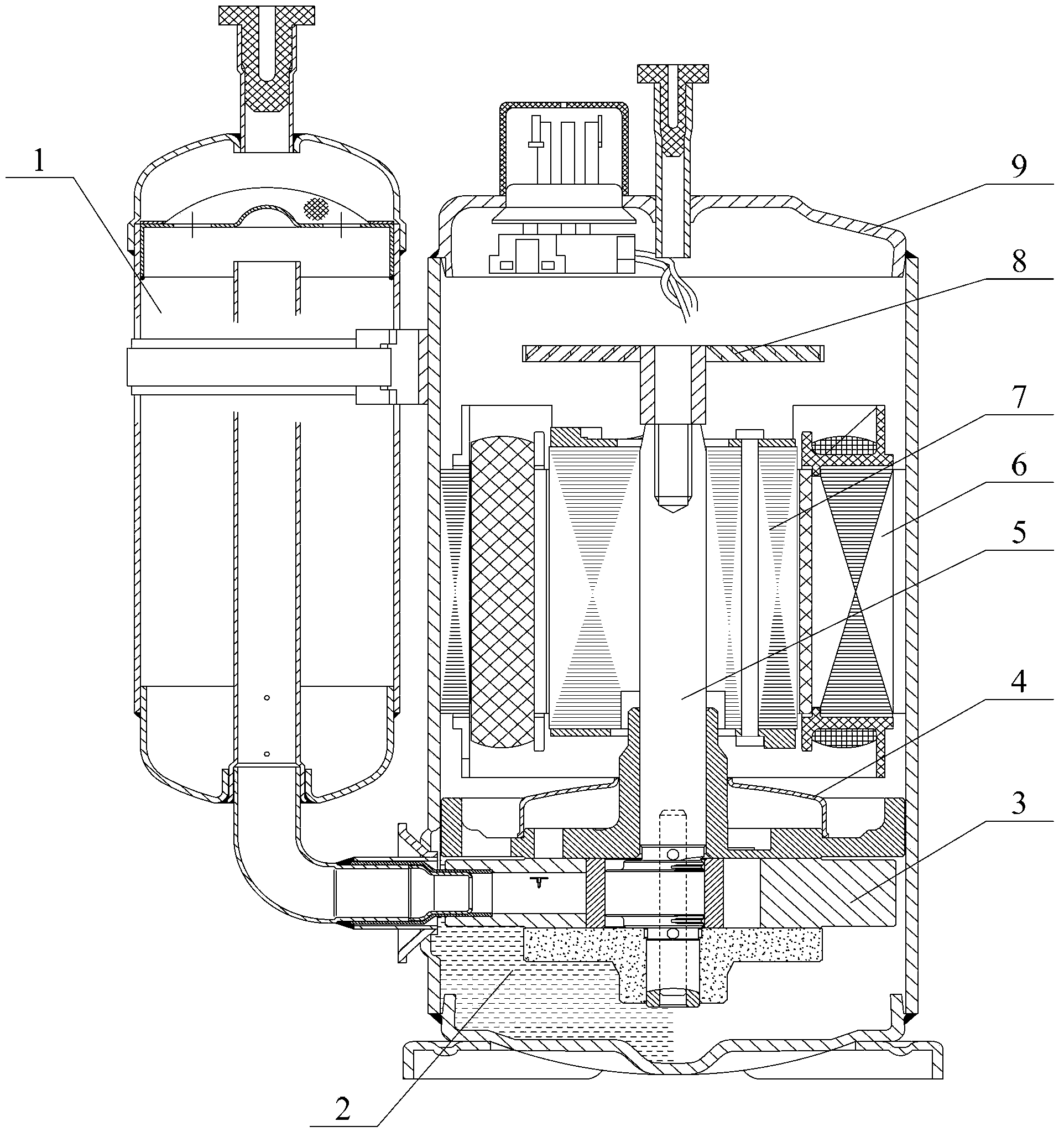
[0031] like figure 1 As shown, after the stator 6 and rotor 7 of the compressor are energized, they form a motor that drives the crankshaft 5 to rotate. Driven by the stator 6 and rotor 7, the crankshaft 5 can drive the rolling rotor connected to it to move in the cylinder 3, so that the low-pressure gas It is sucked into the compressor from the gas cylinder 1, and at the same time, the rotation of the rolling rotor compresses the low-pressure gas into high-pressure...


PUM


Abstract

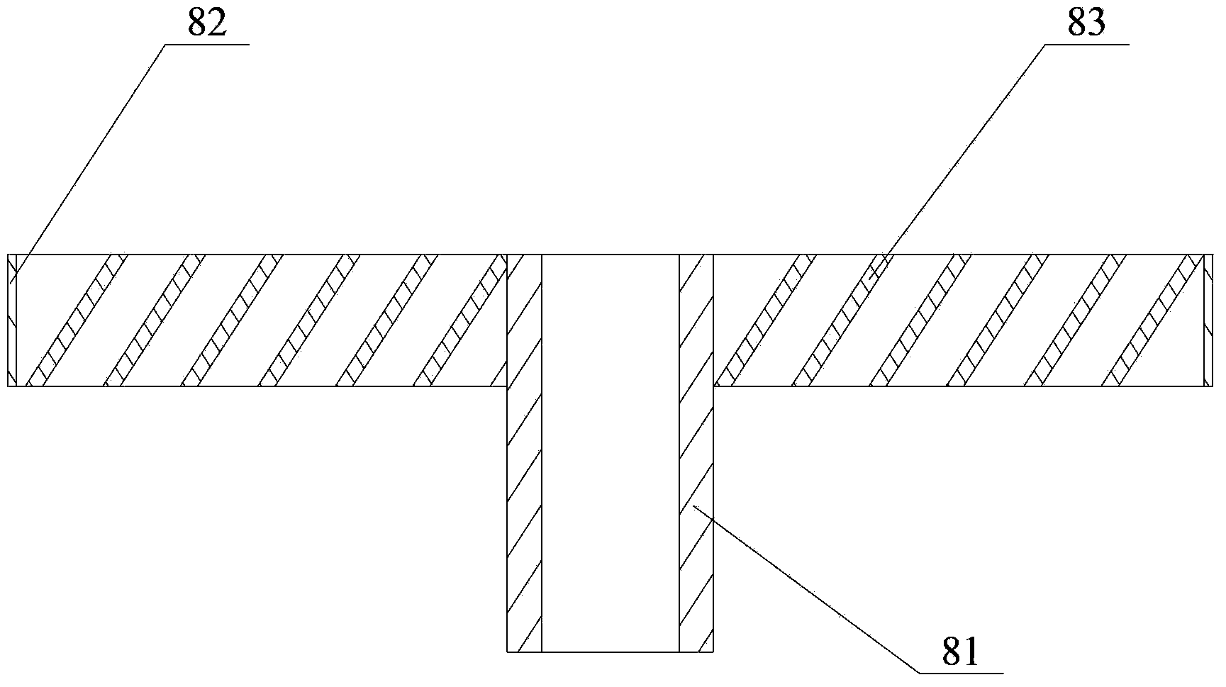
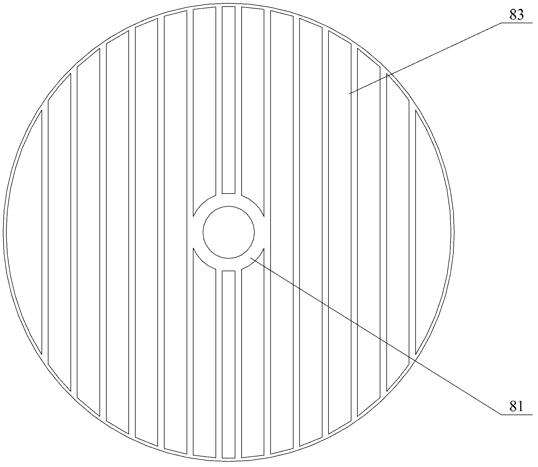
The invention discloses an oil baffle plate. The oil baffle plate is connected to the upper end of a crank shaft and comprises a transmission part fixedly connected with the crank shaft and an oil-gas separation part vertically arranged at the upper end of the transmission part, wherein the oil-gas separation part is provided with a plurality of strip-shaped fan blades which are obliquely distributed relative to the axis of the crank shaft. After the oil baffle plate is connected to the upper end of the crank shaft and an oil-gas mixture flows through the oil baffle plate, the oil-gas mixture suffers from a centrifugal force under the rotary effect of each strip-shaped fan blade; the mass of freezing oil is obviously greater than that of high-pressure gas so that the freezing oil is thrown to the outer edge of the oil baffle plate and the high-pressure gas is gathered at the central position of the oil baffle plate; meanwhile, the collision area of the oil-gas mixture and the oil baffle plate is enlarged under the effect of each strip-shaped fan blade so that the high-pressure gas and the freezing oil are easy to separate. The oil baffle plate provided by the invention can be used for easily separating the freezing oil mixed with the high-pressure gas so as to reduce the freezing oil flowing out from a compressor. The invention further discloses the compressor with the oil baffle plate.

Description

technical field [0001] The invention relates to the technical field of compression equipment, in particular to an oil baffle. The present invention also relates to a compressor with the above-mentioned oil baffle. Background technique [0002] Compressor is a driven fluid machine that raises the pressure of gas from low pressure to high pressure. According to its working principle, it can be divided into volume type and speed type. Rotary compressor is a common type of volume type. Its application With the continuous development of the economy, the scope becomes wider and wider. [0003] The rotary compressor mainly includes a shell and a stator, a rotor, a crankshaft, a muffler, a cylinder, and a rolling rotor arranged in the shell. The stator and the rotor form a motor that drives the crankshaft to rotate, and the crankshaft can be driven by the stator and the rotor. Connect with it The rolling rotor moves in the cylinder, so that the low-pressure gas is sucked into the ...

Claims


Application Information

Patent Timeline
Patent Type & Authority Applications(China)
IPC IPC(8): F04C29/00
Inventor 李健宝李万涛
Owner ZHUHAI GREE REFRIGERATION TECH CENT OF ENERGY SAVING & ENVIRONMENTAL PROTECTION
Learn More