Novel energy-saving lamp

An energy-saving lamp, a new type of technology, applied in the cooling/heating device of lighting device, lighting and heating equipment, slender light source, etc., can solve the problems of reducing the effective light-emitting area of ​​the lamp tube, shortening the service life of the cathode, and accumulating heat of the lamp tube. , to increase the effective luminous area, prevent mosquito dust and reduce damage

Inactive Publication Date: 2014-02-12
WUNING HUAYANG IND
View PDF6 Cites 0 Cited by
  • Summary
  • Abstract
  • Description
  • Claims
  • Application Information

AI Technical Summary

Problems solved by technology

At present, the structure of the traditional energy-saving lamp is composed of the upper lamp holder, the middle ballast cover, the bottom lamp tube and the energy-saving electronic rectifier. The thermal damage caused by heat accumulation and heating of the rectifier will damage the service life of the energy-saving electronic rectifier; after the lamp works normally, there will always be current passing through the filament in the filament circuit, thus forming an emission current and shortening the service life of the cathode. The phenomenon of warming effect that accelerates the accumulated heat
Moreover, the energy-saving lamp is composed of a plurality of straight U-shaped lamp tubes. The fluorescent light emitted by the energy-saving lamps is absorbed by the shells of each other's lamp tubes, resulting in a relative reduction in the effective light-emitting area of ​​the lamp tubes and a decrease in the light efficiency of the entire lamp.

Method used


Image

  • Novel energy-saving lamp

Examples


Embodiment Construction

[0013] In order to make the technical means, creative features, goals and effects achieved by the present invention easy to understand, the present invention will be further described below in conjunction with specific illustrations.

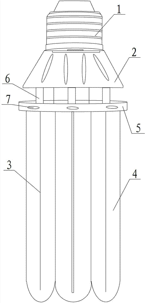
[0014] see figure 1 A new type of energy-saving lamp, comprising a lamp cap 1, a ballast cover 2, a filament 3, a lamp tube 4, an energy-saving electronic rectifier, a lamp tube connection heat shield 5, a screw connection column 6, and a cooling hole 7.

[0015] In this embodiment, the filament 3 is installed in the lamp tube 4, the inner wall of the lamp tube 4 is sprayed with rare earth powder, the energy-saving electronic rectifier is installed in the ballast cover 2, and the lamp tube connection heat shield 5 is arranged between the lamp tube 4 and the ballast. At the junction of the flow device cover 2, the upper end surface of the lamp tube connected to the heat shield 5 is provided with a screw connection column 6 and a wick wire sheath ...


PUM


Abstract

The invention discloses a novel energy-saving lamp. The novel energy-saving lam comprises a lamp holder, a ballast cover, a lamp filament, a tube, an energy-saving electronic rectifier and a tube connected thermal protection shield, wherein the lamp filament is installed in the tube; rare earth powder is sprayed on the inner wall of the tube; the energy-saving electronic rectifier is installed in the ballast cover; the tube connected thermal protection shield is arranged at the combing part of the tube and the ballast cover; a screw connecting column and a lamp wick wire jacket base are arranged on the upper end surface of the tube connected thermal protection shield; a cavity is arranged at the lower end of the tube connected thermal protection shield; a positioning base and a control system are arranged in the cavity; a radiator is arranged in the tube connected thermal protection shield; heat emission holes are formed in the tube connected thermal protection shield; and the radiator is connected with the control system. The novel energy-saving lamp has the advantages that the tube connected thermal protection shield is arranged at the combining part of the tube and the ballast cover and adopts a rotatable structure, and a self-locking buckle is arranged on the inner wall of the tube connected thermal protection shield, so that the novel energy-saving lamp can not only emit heat inside the tube and reduce accumulated heat heating inside the energy-saving lamp, but also effectively prevent mosquitoes and dust from entering the lamp and increase the service life of the tube.

Description

technical field [0001] The invention relates to the technical field of energy-saving lamps, in particular to a novel energy-saving lamp. Background technique [0002] Energy conservation is a major problem faced by all human beings, and it is also one of the main goals that human beings work together to pursue effectively. At present, the structure of the traditional energy-saving lamp is composed of the upper lamp holder, the middle ballast cover, the bottom lamp tube and the energy-saving electronic rectifier. The thermal damage caused by heat accumulation and heating of the rectifier will damage the service life of the energy-saving electronic rectifier; after the lamp works normally, there will always be current passing through the filament in the filament circuit, thus forming an emission current and shortening the service life of the cathode. The warming effect phenomenon that accelerates the accumulated heat. Moreover, the energy-saving lamp is composed of a plurali...

Claims


Application Information

Patent Timeline
Patent Type & Authority Applications(China)
IPC IPC(8): F21S2/00F21V29/00F21V31/00F21V9/00F21Y103/02F21V29/50F21V29/83F21Y103/30
Inventor 段维维
Owner WUNING HUAYANG IND
Why Eureka
Try Eureka