indoor ventilation device

A ventilation device and building technology, applied in ventilation systems, space heating and ventilation, pipeline layout, etc., can solve the problems of reduced fresh air volume, poor operation management, etc., and achieve the effects of increasing comfort, convenient use, and easy promotion

Inactive Publication Date: 2017-01-18
兰州云式环境科技有限公司
View PDF5 Cites 0 Cited by
  • Summary
  • Abstract
  • Description
  • Claims
  • Application Information

AI Technical Summary

Problems solved by technology

Most modern buildings are equipped with air-conditioning systems. From the perspective of energy conservation, the amount of fresh air entering the room through the air-conditioning system is reduced. At the same time, the air-conditioning system may also become a breeding ground for certain germs and viruses and a medium for cross-infection due to poor operation and management.

Method used


Image

  • indoor ventilation device
  • indoor ventilation device

Examples


Embodiment 1

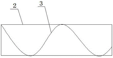
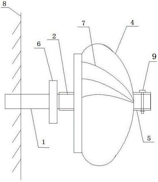
[0029] Pass one end of the hollow tube I1 through the side wall of the building and fix it to ensure that it runs through the wall. The end of the hollow tube I1 equipped with an openable sealing cover is located indoors. After the other end of the hollow tube Ⅰ1 extends out of the wall for a certain distance, the outer port of the hollow tube Ⅰ1 is connected with the hollow tube Ⅱ2, and the fan is installed on the hollow tube Ⅱ2, and the direction of the arc-shaped blade 7 on the arc surface of the turbine head 4 in the fan is aligned with the direction of the hollow tube Ⅱ2. The directions of the helical blades 3 in the hollow circular tube II2 are consistent, and then the hollow tube II2 and the hollow shaft tube 5 of the fan are fixed by captive screws 9 .

[0030] When there is wind in the external environment, an airflow flowing along the direction of the wall will be formed under the action of the outer surface. After the arc-shaped blade 7 of the fan is stressed, the tu...

Embodiment 2

[0032] Pass one end of the hollow circular tube I1 through the side wall of the building and fix it to ensure that it runs through the wall. The end of the hollow circular tube I1 equipped with an openable sealing cover is located indoors. After the other end of the hollow tube Ⅰ1 extends out of the wall for a certain distance, the outer port of the hollow tube Ⅰ1 is connected with the hollow tube Ⅱ2, and the fan is installed on the hollow tube Ⅱ, and the arc-shaped blades on the arc surface of the turbine head 4 in the fan are The direction of 7 is opposite to the direction of the helical blade 3 in the hollow circular tube II2, and then the hollow tube II2 and the hollow shaft tube 5 in the fan are fixed by captive screws 9.

[0033] When there is wind in the external environment, the airflow flowing along the direction of the wall will also be formed under the action of the outer surface. After the arc blade 7 of the fan is stressed, the turbine head 4 can rotate under the a...


PUM


Abstract

The invention discloses an indoor ventilation device of a building. The indoor ventilation device comprises a hollow pipe I, a hollow pipe II and a fan, wherein the fan is composed of a turbine head and a hollow shaft tube; the central shaft of the turbine head is provided with the hollow shaft tube; the hollow shaft tube is sleeved with the hollow pipe II; the hollow pipe II is connected with the hollow pipe I by a bearing; the arc-shaped surface of the turbine head is provided with an arc-shaped fan blade; a helical blade is arranged at the inner wall of the hollow pipe II; an opening and closing seal cover is arranged at one end of the hollow pipe I. The periphery of the fan is provided with the arc-shaped fan blade, the mounting direction of the fan can be adjusted, thus the air flow direction can be adjusted, fresh air can be flowed into the interior, and indoor dirty air can be pumped out of the interior by adjusting the fan; the contradictory issue between energy conservation and ventilation can be solved, the ventilation and air exchange can be carried out by using external natural wind power and are free of the limit of time; the outward fan blade is filled inside an air exchange pipeline port, and the indoor airtight requirement of the building can be met.

Description

technical field [0001] The invention relates to the field of building ventilation, in particular to a building indoor ventilation device. Background technique [0002] In modern life, people spend more than 80% of their time indoors, and the sick building syndrome caused by indoor air quality problems greatly affects people's physical and mental health, resulting in reduced social work efficiency and increased medical expenses. Higher social issues also received extensive attention. People have realized the importance and urgency of indoor air quality problems. [0003] In severely polluted indoor air, there are tens of thousands of microorganisms per cubic meter, mainly from the human body. Speaking, coughing and sneezing can eject microorganisms in the mouth and respiratory tract; a cold patient can eject 15-15,000 infectious doses of virus particles in one sneeze. Microorganisms carried on the skin and clothing can be scattered into the air with daily activities. A mo...

Claims


Application Information

Patent Timeline
Patent Type & Authority Patents(China)
IPC IPC(8): F24F7/06F24F13/06
Inventor 王厚成李凤曾正中南忠仁程世红梁鹏贾海明
Owner 兰州云式环境科技有限公司
Why Eureka
Try Eureka