System and method for isolating voltage sensor faults, contactor faults in electrical systems

A technology of voltage sensor and contactor, applied in the direction of measuring current/voltage, instrument, measuring electricity, etc., can solve the problems of complicated diagnosis and isolation, failure of voltage sensor, etc.

Active Publication Date: 2017-03-01
GM GLOBAL TECH OPERATIONS LLC
View PDF6 Cites 0 Cited by
  • Summary
  • Abstract
  • Description
  • Claims
  • Application Information

AI Technical Summary

Problems solved by technology

However, voltage sensors used to detect stuck contactor conditions may fail, thereby complicating the diagnosis and isolation of stuck contactor failures and stuck-in-range voltage sensor failures

Method used


Image

  • System and method for isolating voltage sensor faults, contactor faults in electrical systems
  • System and method for isolating voltage sensor faults, contactor faults in electrical systems
  • System and method for isolating voltage sensor faults, contactor faults in electrical systems

Examples


Embodiment Construction

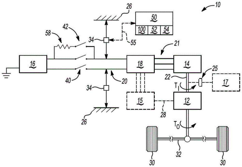
[0016] Referring to the drawings, in which like reference numerals refer to like parts, and with figure 1 Initially, an exemplary vehicle 10 is shown including a voltage source in the form of a battery pack 16 , a voltage sensor 34 , a set of solid state contactors 40 and a controller 50 . see below Figure 2-4 Described in detail, the control 50 is configured to selectively perform the steps of the method 100 to isolate high voltage electrical faults on the vehicle 10, specifically a "stuck in range" fault of the voltage sensor 34 and a "bonded closed" of the contactor 40 Fault. The method 100 can be used in any electrical system that employs a voltage source, be it a battery, fuel cell, capacitor, or other electrical or chemical voltage source, via a mechanical / solid state switch, relay, or The contactor 40 is disconnected from the electrical load by actuation of the similar contactor. However, for consistency of description, the exemplary vehicle 10 will be described in ...


PUM


Abstract

A method for isolating from a contactor fault and a voltage sensor fault in an electrical system, comprising measuring a voltage between ground and a voltage bus rail when the contactor is open, and comparing the measured voltage to a first threshold voltage In comparison, this first threshold corresponds to the calibrated voltage reading expected when the contactor is closed. A first diagnostic code is recorded as a stuck-in-range fault condition of the sensor when the measured voltage is greater than zero and less than the first threshold voltage. When the measured voltage is equal to the first threshold voltage, a second diagnostic code is recorded with the bonded closed state of the contactor. The measured voltage may be compared with a second threshold voltage exceeding the first threshold voltage, and when the measured voltage exceeds the first threshold voltage or is less than zero, a third diagnostic code is recorded as a short circuit value of the sensor.

Description

technical field [0001] The present invention relates to systems and methods for isolating voltage sensor and contactor faults in electrical systems. Background technique [0002] In hybrid and battery electric vehicles, a high voltage DC battery pack provides a portion of the power needed to propel the vehicle. The battery pack powers the inverter modules on the high voltage DC bus. The inverter module converts the DC voltage from the battery pack to an AC waveform and thereafter energizes one or more motor / generator units with the AC waveform on the high voltage AC bus. Torque from the motor / generator unit(s) can thereafter be used to provide input torque to the transmission, or to generate electricity for recharging the battery pack. [0003] The battery pack may be partially electrically isolated from the vehicle chassis and electrical components of the vehicle powertrain by selectively opening the solid state contactor under some operating conditions, such as when the ...

Claims


Application Information

Patent Timeline
Patent Type & Authority Patents(China)
IPC IPC(8): G01R19/165G01R31/00
CPCG01R35/00B60L3/04G01R31/52
Inventor W.M.拉扎尔二世D.P.格伦
Owner GM GLOBAL TECH OPERATIONS LLC
Why Eureka
Try Eureka