Imaging device
A camera device and image technology, applied in measuring devices, photography, image communication, etc., to achieve the effect of improving responsiveness and reducing changes
- Summary
- Abstract
- Description
- Claims
- Application Information
AI Technical Summary
Problems solved by technology
Method used
Image
Examples
Embodiment 1
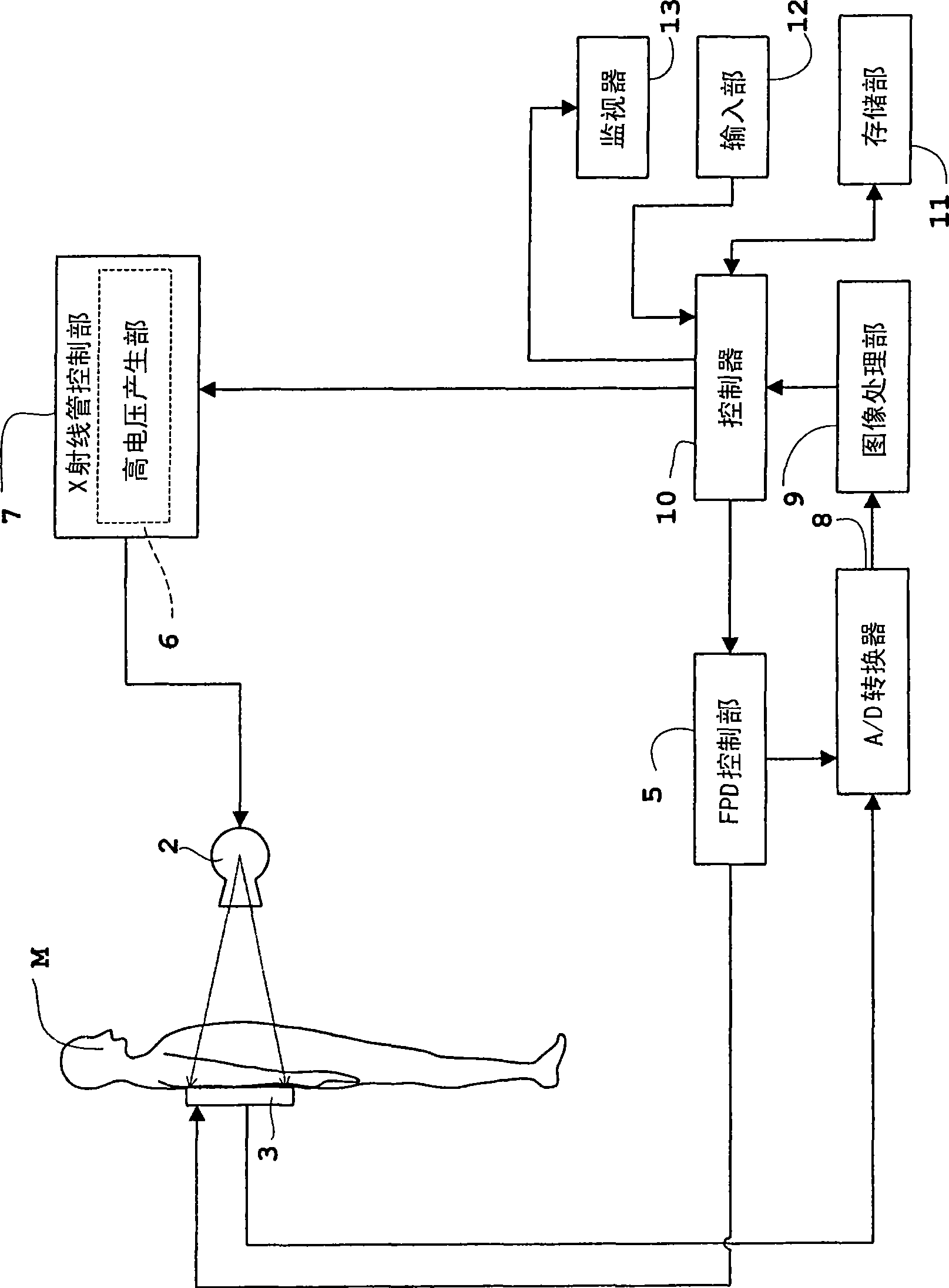
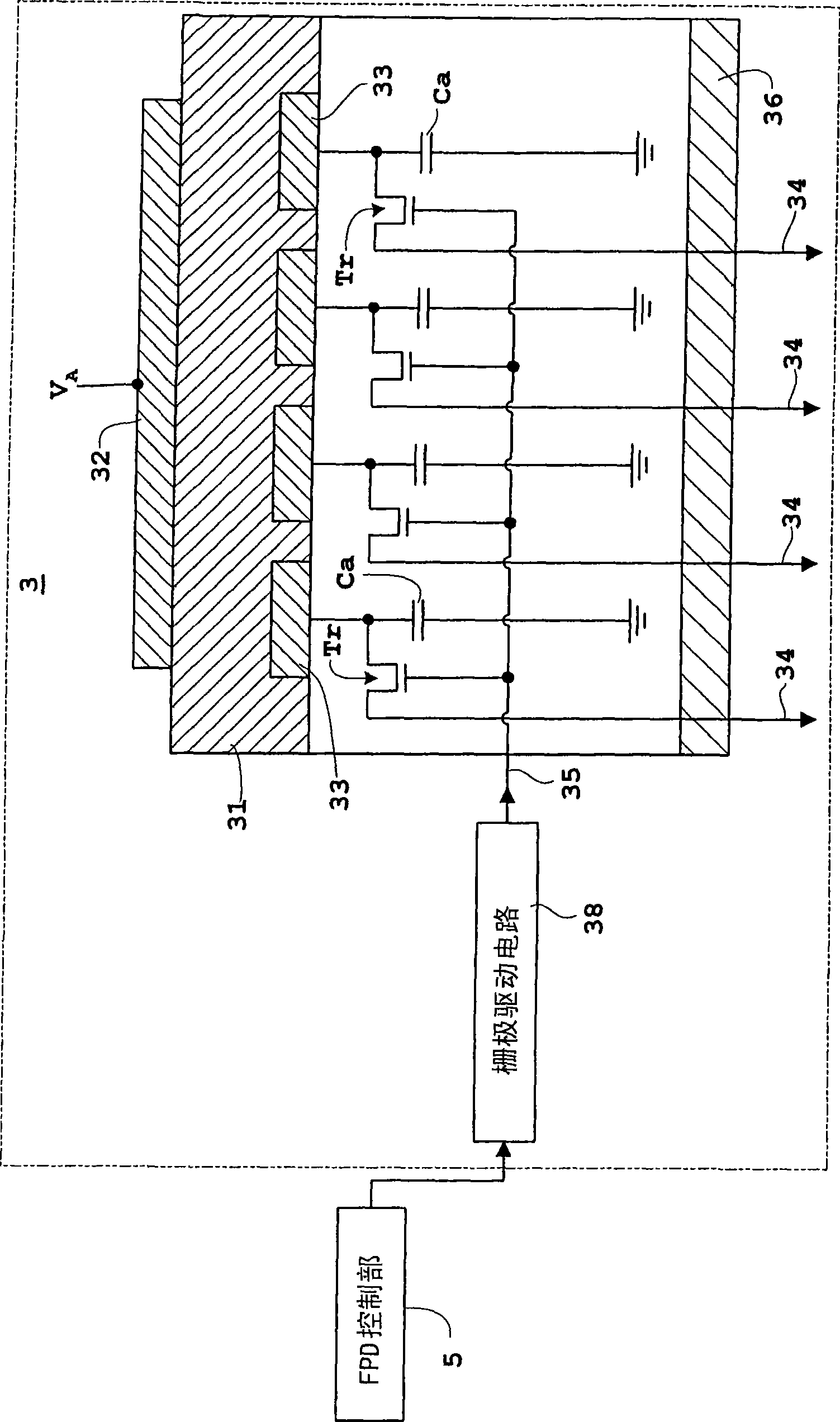
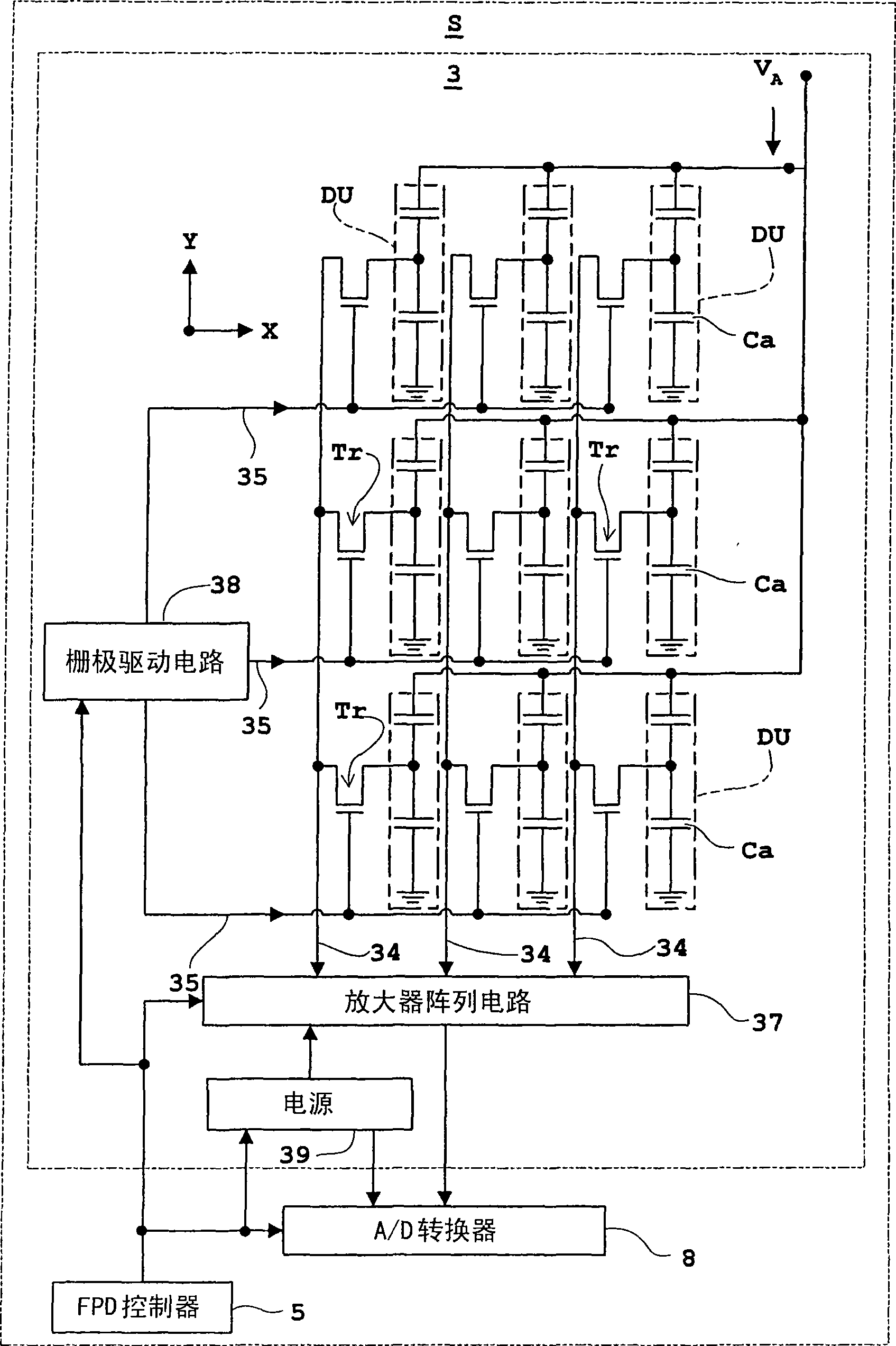
[0072] Hereinafter, Embodiment 1 of the present invention will be described with reference to the drawings. figure 1 is a block diagram of the X-ray imaging device of each embodiment, figure 2 is an equivalent circuit of a flat-panel X-ray detector viewed from the side for an X-ray imaging device, image 3 It is an equivalent circuit of a flat-panel X-ray detector viewed from above. In this Embodiment 1, also in Embodiments 2 to 4 mentioned later, a flat-panel X-ray detector (hereinafter, appropriately referred to as "FPD") is used as an example as a light or radiation detector, and as a The imaging device will be described by taking an X-ray imaging device as an example. In addition, the X-ray imaging device and FPD of each embodiment, and Figure 1~3 constitute the same.
[0073] The X-ray imaging device in Embodiment 1 also includes the X-ray imaging devices in Embodiments 2 to 4 mentioned later, such as figure 1 As shown, an X-ray tube 2 for irradiating X-rays to a...
Embodiment 2
[0117] Next, Embodiment 2 of the present invention will be described with reference to the drawings. Figure 8 It is a timing diagram of each frame rate and each signal related to it in Embodiment 2. The X-ray imaging device and the FPD of the second embodiment have the same configuration as that of the first embodiment, so the description thereof will be omitted, and only the points of difference will be described.
[0118] The difference with embodiment 1 is: controller 10 (referring to figure 1 ) has a region change function capable of changing the region where the readout of carriers at the time of irradiation is started. In addition, the readout of carriers during irradiation is performed periodically in the order from the first region to the adjacent divided regions, and the last region ( Figure 8 D4 in ) Once finished, return to the original area ( Figure 8 Be D1 in the middle), carry out repeatedly, be identical with embodiment 1 at this point. In addition, in t...
Embodiment 3
[0130] Next, Embodiment 3 of the present invention will be described with reference to the drawings. Figure 10 It is a timing chart of each frame rate and each signal related thereto in the third embodiment. The X-ray imaging device and FPD of the third embodiment are also configured in the same manner as those of the above-mentioned first and second embodiments, so description thereof will be omitted, and only differences will be described.
[0131] The difference from Examples 1 and 2 is that the readout of carriers during irradiation is performed continuously over the entire area of the image. In addition, in the order of the adjacent regions to be divided ( Figure 10 In the order of D1, D2, D3, D4) the readout of carriers before irradiation is performed periodically, and the last area ( Figure 10 Once the readout of carriers in D4) ends, it returns to the original area ( Figure 10 D1) is repeated, and it is the same as in Examples 1 and 2 at this point.
[0132] ...
PUM
 Abstract
Description
Claims
Application Information
 - R&D
- Intellectual Property
- Life Sciences
- Materials
- Tech Scout
- Unparalleled Data Quality
- Higher Quality Content
- 60% Fewer Hallucinations
Browse by: Latest US Patents, China's latest patents, Technical Efficacy Thesaurus, Application Domain, Technology Topic, Popular Technical Reports.
© 2025 PatSnap. All rights reserved.Legal|Privacy policy|Modern Slavery Act Transparency Statement|Sitemap|About US| Contact US: help@patsnap.com


