Seismic source location method eliminating influences of velocity errors

A technology for seismic source location and velocity elimination, which is applied in the field of resource mining and seismic exploration, can solve the problems of velocity model inversion difficulties, multiple solutions, and large errors, and achieve the effect of eliminating strong dependence

Active Publication Date: 2014-02-12
CHINA PETROLEUM & CHEM CORP +1
View PDF2 Cites 4 Cited by
  • Summary
  • Abstract
  • Description
  • Claims
  • Application Information

AI Technical Summary

Problems solved by technology

The first factor is mainly determined by the completeness of the observation data. Due to the limitations of the observation system, the inversion of the velocity model is often very difficult, mainly manifested in multiple solutions and relatively large errors. The second factor is mainly related to the instrument and Relevant operators are related, which is an objective and unchangeable factor

Method used


Image

  • Seismic source location method eliminating influences of velocity errors
  • Seismic source location method eliminating influences of velocity errors
  • Seismic source location method eliminating influences of velocity errors

Examples


Embodiment 1

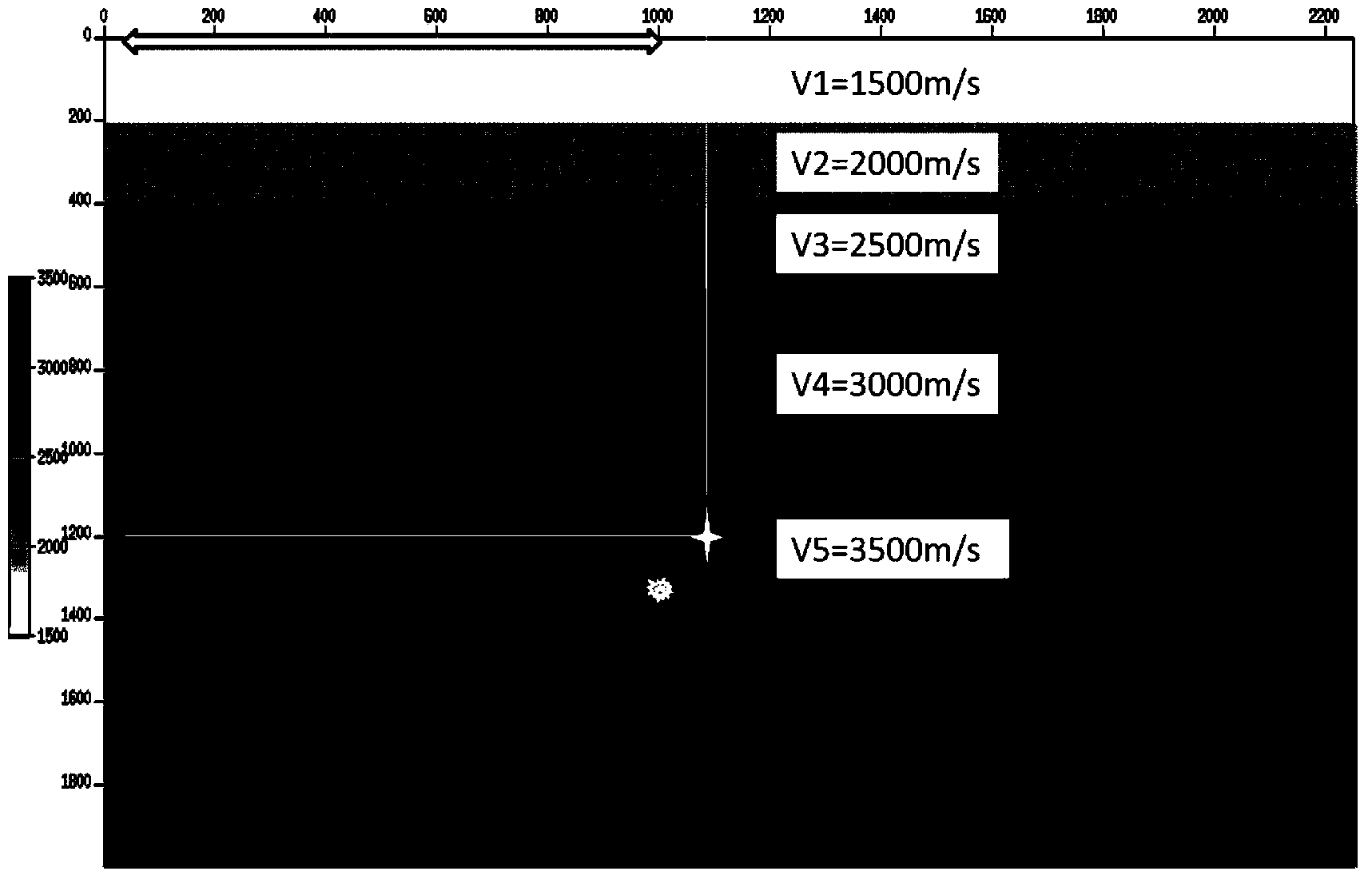
[0061] Example 1 uses a theoretical model for testing. figure 1 It is the diagram of the model in Example 1, with five layers in total, the speed of each layer is V1, V2, V3, V4, V5, and two seismic sources A and B are placed, wherein the asterisk is the seismic source A, and the circle is the seismic source B. Point A is set at (1100, 1200), point B is set at (950, 1350), and the ground observation position is (10-1000) meters, as shown by the arrow in the figure, A is a known point, and B is the position to be positioned point.

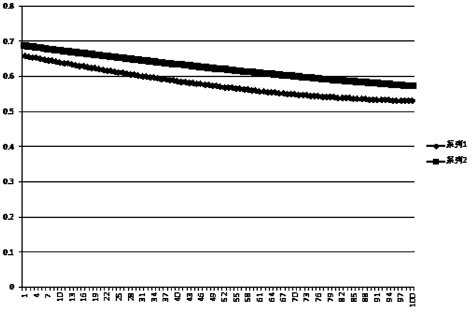
[0062] figure 2 is the observed travel time (that is, when the observations of A and B arrive, steps 1, 2, and 3 are used), figure 2 Series 1 is the curve at point A, series 2 is the curve at point B, ( figure 2 The middle thick line (above) is series 2) The time unit is seconds. Table 1 shows the positioning of seismic source point B by using the present invention under different models. In the model, only the velocity changes, and the depth...

Embodiment 2

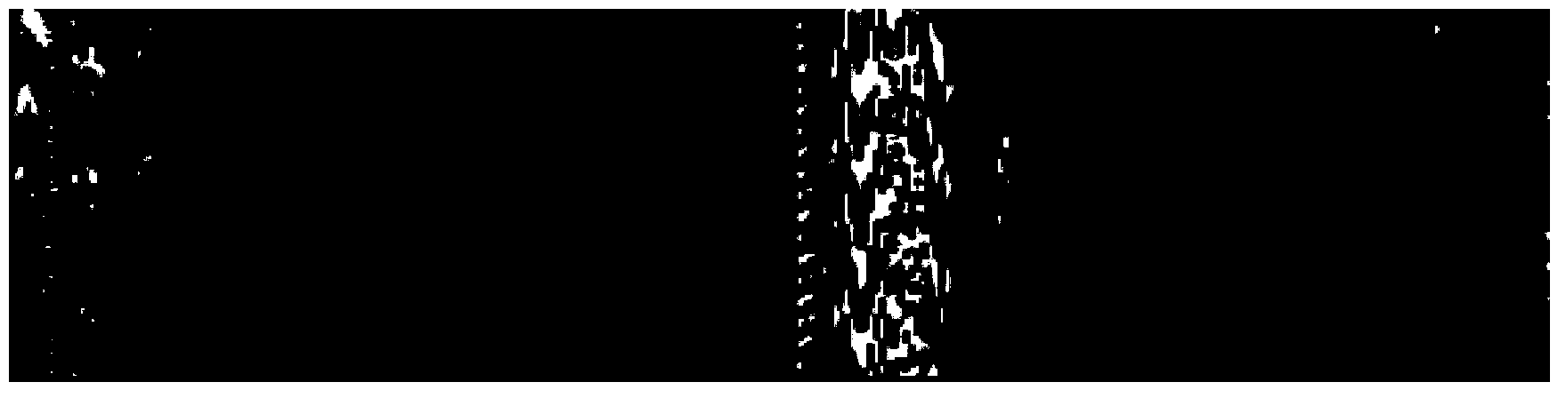
[0068] image 3 It is the profile of the source A observed by a certain actual data, two observation lines in different orientations (the arrangement of the receiver points, a total of two lines of receivers are received, and one observation line refers to the arrangement of many receivers along a certain line. ), where the position of point A is known as (3353126.0, 338361.0, 2145.1).

[0069] Figure 4 It is the profile of source B observed by some actual data, and the location of source B is unknown.

[0070] Figure 5-1 is true image 3 The travel time picked up after performing residual correction (residual correction is a correction method in seismic exploration, using mathematical methods to eliminate small time difference changes in seismic traces to make the time curve smoother), Figure 5-2 is true Figure 4 Travel time picked up after residual correction (for image 3 and Figure 4 The travel time picked up after residual correction is Figure 5-1 and Figu...


PUM


Abstract

The invention provides a seismic source location method eliminating influences of velocity errors, and belongs to the field of seismic exploration. According to the method, a velocity error model related to velocity is obtained through a given seismic source position, the velocity error model is applied to an objective function, all the possible seismic source positions are scanned, and the coordinate of the point which enables the value of the objective function to be minimum is the coordinate of the seismic source to be located. The method eliminates the strong dependence of seismic locating accuracy on the velocity model, can achieve accurate location on the seismic source, changes of subsurface structures and fluid can be detected through the accurate location on the seismic source, and therefore the exploitation and the extraction of petroleum, natural gas and the like can be further guided.

Description

technical field [0001] The invention belongs to the field of seismic exploration, and specifically relates to a seismic source positioning method for eliminating the influence of velocity errors, which is mainly used in the field of resource mining, including seismic exploration fields such as coal, oil, and natural gas, and can also be used for engineering geophysical monitoring and conventional natural gas exploration. Earthquake location. Background technique [0002] Earthquake location is one of the most basic issues in seismology, and it is of great significance to the study of such basic issues in seismology as seismic active structure, the internal structure of the earth, and the geometric structure of the earthquake source. The problem of earthquake location is simply summarized as follows: according to the observation data of the arrival time of the earthquake at the station, the spatial coordinates of the source and the time of the earthquake are determined, and s...

Claims


Application Information

Patent Timeline
Patent Type & Authority Applications(China)
IPC IPC(8): G01V1/28
Inventor 朱海波
Owner CHINA PETROLEUM & CHEM CORP
Why Eureka
Try Eureka