
Lining core automatic detection device

The technology of an automatic detection device and a lining core, which is applied in the field of automobile brakes, can solve the problems of difficult insertion of pins into the central through hole, failure to brake in time, and low detection efficiency, and achieves compact and simple mechanism structure and reasonable overall layout. Orderly, good detection effect

Active Publication Date: 2014-02-12
宁波名古屋工业有限公司
View PDF6 Cites 1 Cited by
  • Summary
  • Abstract
  • Description
  • Claims
  • Application Information

AI Technical Summary

Problems solved by technology

[0004] Because the above-mentioned detection method is a manual detection method, there are inherent shortcomings of manual detection: the insertion speed is slow, resulting in low detection efficiency
In addition, because the diameter of the central through hole of the lining core is small, only 0.5mm, and the pin is thinner, it is not easy for the worker to insert the pin into the central through hole accurately at one time. When fatigued, it is likely to be inserted several times before it can be inserted into the center through hole smoothly, which seriously reduces the insertion speed
What's more serious is that after a long period of testing, workers are likely to experience dizziness and fatigue, which will lead to false detection and missed detection, which cannot guarantee the quality of the inspection of the lining core. Once the above situation occurs, it is very likely It is possible that the unqualified product whose center through hole is not smooth can be used as a qualified product in the braking system, and the unqualified lining core will block the supply of oil circuit when braking, and the entire brake system will be damaged. The system breaks down, but cannot brake in time, resulting in unpredictable and serious consequences

Method used


Image

  • Lining core automatic detection device
  • Lining core automatic detection device
  • Lining core automatic detection device

Examples


Embodiment Construction

[0021] The present invention will be described in further detail below in conjunction with the accompanying drawings.

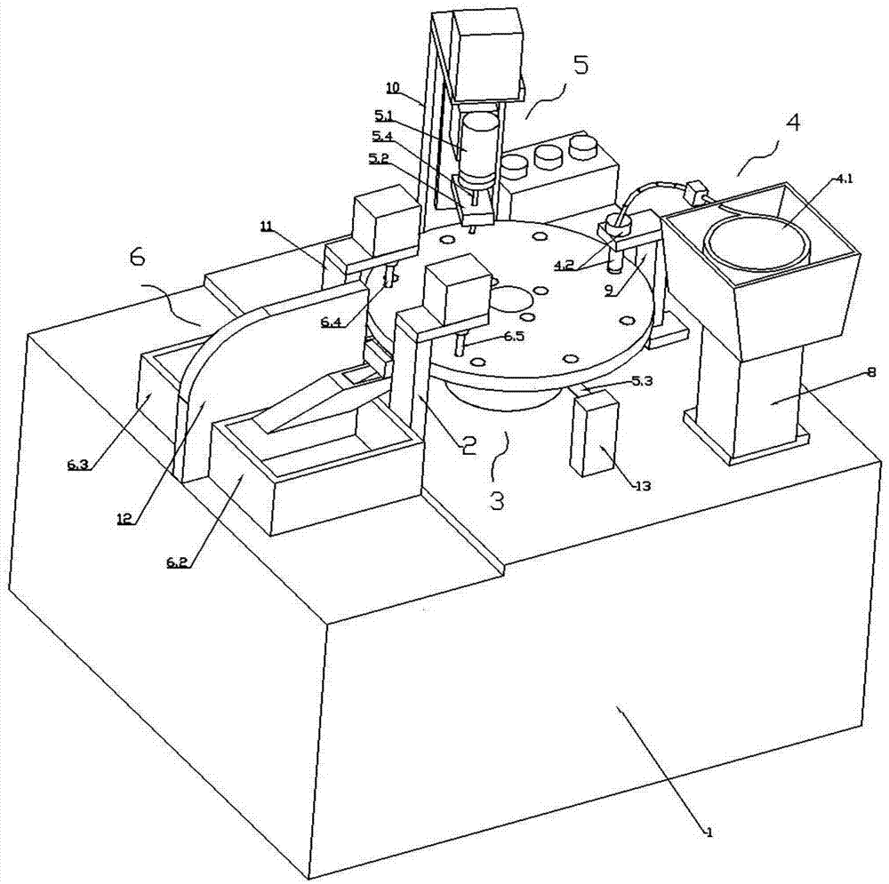
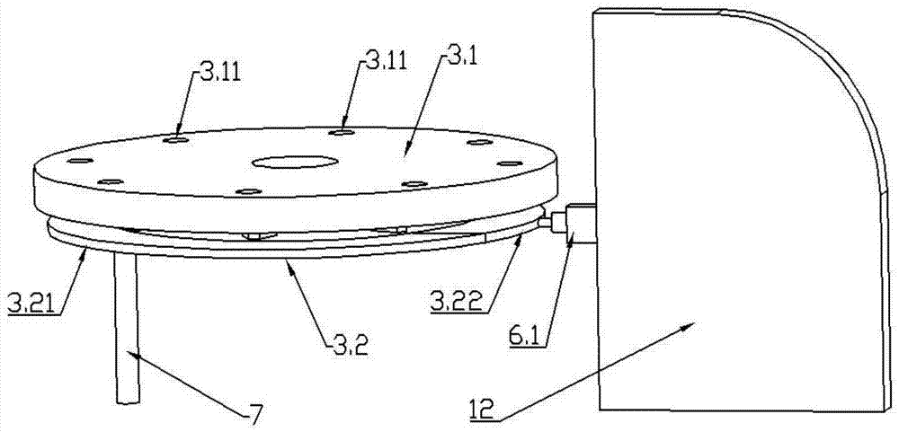
[0022] As shown in the figure, a liner automatic detection device includes a machine base 1, a controller (located in the machine base 1, not shown), a turntable rotation mechanism 3 located on the machine base 1, and a driving turntable rotation mechanism 3 to realize rotation The deceleration motor (located in the machine base 1, not shown), the conveying mechanism 4 installed on the machine base 1 to transport the product to the turntable rotation mechanism 3 for detection, and the detection of the product that has been transported to the turntable rotation mechanism 3 Institution 5. A collection institution 6 that classifies and collects the tested products.

[0023] The conveying mechanism 4 , detecting mechanism 5 , and collecting mechanism 6 are arranged around the turntable rotating mechanism 3 and are sequentially arranged in a circumferential arrang...


PUM


Abstract

The invention discloses a lining core automatic detection device which comprises a machine base (1), a controller, a speed reduction motor, a rotating disc rotating mechanism (3) arranged on the machine base (1), a conveying mechanism (4), a detection mechanism (5) and a collecting mechanism (6). The conveying mechanism (4) is installed on the machine base (1) and used for conveying products to the rotating disc rotating mechanism (3), the detection mechanism (5) detects the products which are arranged on the rotating disc rotating mechanism (3) and required to be detected, and the collecting mechanism (6) is used for conducting separate collection on the detected products. The conveying mechanism (4), the detection mechanism (5) and the collecting mechanism (6) are arranged by surrounding the rotating disc rotating mechanism (3) and are sequentially and circumferentially arranged in the rotating direction of the rotating disc rotating mechanism (3), the rotating disc rotating mechanism (3) is connected with an output shaft of the speed reduction motor, and the speed reduction motor, the conveying mechanism (4), the detection mechanism (5) and the collecting mechanism (6) are electrically connected with the controller. The detection device is high in detection speed, capable of effectively improving the detection efficiency and capable of effectively ensuring the detection quality.

Description

technical field [0001] The invention relates to the technical field of automobile brakes, in particular to an automatic detection device for a lining core used to detect whether the central hole of the lining core is unobstructed. Background technique [0002] Such as figure 1 As shown, it is a lining core used in the brake system of an automobile. The lining core is provided with a central through hole. Whether the through hole is smooth or not plays a decisive role in the smooth flow of the oil passage. [0003] Therefore, when producing the lining core, it is necessary to detect whether the central through hole is unobstructed. At present, the more common detection method is to use manual insertion test, that is, to insert the pin into the central through hole of the lining core manually, if the pin can be inserted smoothly and can protrude from the other end of the lining core , then the lining core meets the requirements of use and is a qualified product, otherwise th...

Claims


Application Information

Patent Timeline
IPC IPC(8): G01V9/00B07C5/36
Inventor 董阿能
Owner 宁波名古屋工业有限公司
Learn More