

Phase shift mask blanks and photomasks for flat panel displays
A flat-panel display and phase-shift mask technology, applied in the field of phase-shift mask blanks and photomasks, can solve the problems of obstructing fine patterns, unclear boundary of the phase-shift layer, affecting the uniformity of the phase-shift layer, etc.
Active Publication Date: 2016-08-17
S & S TECH
View PDF6 Cites 0 Cited by
- Summary
- Abstract
- Description
- Claims
- Application Information
AI Technical Summary
Problems solved by technology
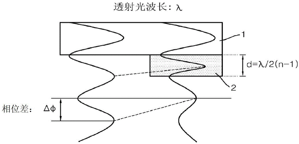
[0009] The slope formed in the pattern edge portion causes a difference in phase change between the pattern edge portion and the remaining portion, and affects the uniformity of the phase shift layer
In addition, the slope of the phase-shift layer in the edge part of the pattern causes the boundary between the phase-shift layers to become unclear, which hinders the formation of fine patterns
Method used
View moreImage
Smart ImageViewing Examples

Examples
Embodiment
[0072] Phase shift layer formation
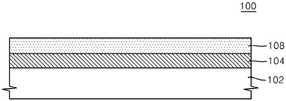
[0073] In order to evaluate a phase shift mask blank according to an exemplary embodiment of the present invention, a multi-layer type phase shift layer was formed on a transparent substrate.
[0074] Specifically, a chromium (Cr) target is used as a sputtering target to form the phase shift layer by means of a sputtering process. In this case, the sputtering process is performed using at least one of the following gases: argon (Ar), nitrogen (N 2 ), carbon dioxide (CO 2 ), methane (CH 4 ), and nitric oxide (NO), and the phase shift layer is formed as a CrCON layer with a thickness of about
[0075] [Table 1]
Login to View More PUM
 Abstract
For the manufacture of large-area flat panel displays (FPDs), the phase shift layer is formed using a multilayer type or continuous layer comprising at least two films containing metal and light elements such as nitrogen (N), oxygen (O) and carbon (C). The multilayer type layer or continuous layer is formed by stacking at least two films having different compositions and different etching rates on a transparent substrate. Therefore, the thickness of the phase shift layer can be reduced, and the slope of the section of the edge portion can be formed steeply during the patterning of the phase shift layer, so that the boundary between the phase shift layer patterns can be clear. As a result, the uniformity of this phase shift layer can be ensured, and thus large-area FPD products with finer patterns can be manufactured.
Description
technical field [0001] The present invention relates to a phase shift mask blank and photomask for a flat panel display (hereinafter FPD), and more particularly, the present invention relates to a mask blank and photomask for a FPD, wherein The slope of the cross section of the phase shift layer pattern may be formed steeply. Background technique [0002] In a lithography process for manufacturing an FPD device or a semiconductor large scale integration (hereinafter referred to as LSI) device, a photomask manufactured from a mask blank is generally used to transfer a pattern. [0003] The mask blank is obtained by forming a thin film containing a metal material on the main surface of a light-transmitting substrate formed of synthetic quartz glass, followed by forming a resist layer on the thin film. The shape of the photomask is formed by patterning the thin film in the mask blank. Here, the films may be classified into a light-shielding layer, an anti-reflective layer (AR...
Claims
Login to View More Application Information
Patent Timeline
 Patent Type & AuthorityPatents(China)
IPC IPC(8): G03F1/26
CPCG03F1/26H01L21/0274
Inventor南基守李东镐朴渊洙徐成旼金荣善
OwnerS & S TECH