
Drive signal generation system

A driving signal and digital waveform technology, applied in the field of driving signal generation system, can solve the problems of increasing circuit area, changing square wave driving signal 112, reducing detection accuracy, etc.

Active Publication Date: 2014-02-12
EGALAX EMPIA TECH INC
View PDF5 Cites 3 Cited by
  • Summary
  • Abstract
  • Description
  • Claims
  • Application Information

AI Technical Summary

Problems solved by technology

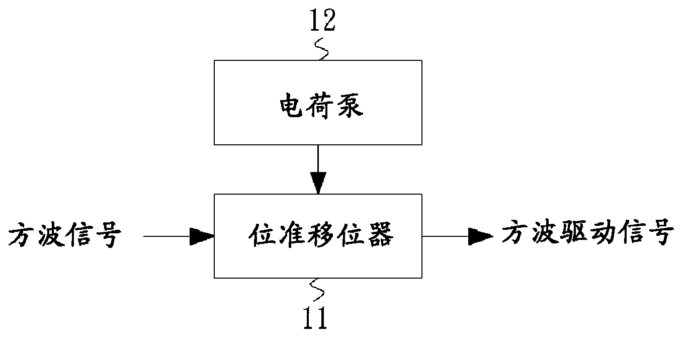
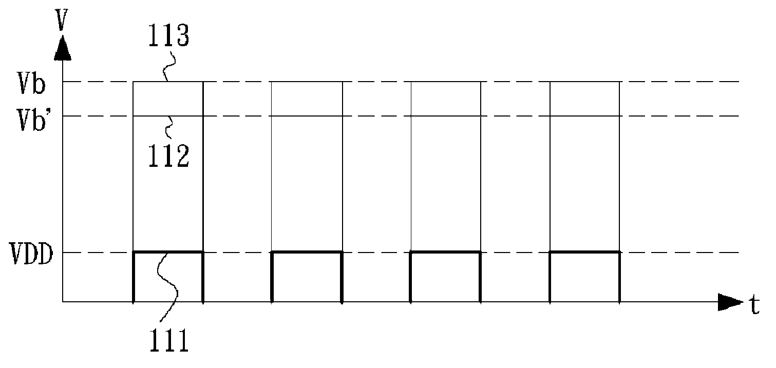
However, since the charge pump 12 will be affected by the power supply provided by the temperature change, the level of the generated square wave driving signal 112 will be changed, resulting in a decrease in detection accuracy, such as Figure 1B Affected square wave drive signal 113 shown in
In order to reduce the influence of temperature, a low dropout (LDO) regulator is generally used for voltage regulation, but it will increase the circuit area

Method used


Image

  • Drive signal generation system
  • Drive signal generation system
  • Drive signal generation system

Examples


Embodiment Construction

[0054] In order to further explain the technical means and effects that the present invention adopts to achieve the intended purpose of the invention, the specific implementation, structure, characteristics and effects of the drive signal generation system proposed according to the present invention will be described below in conjunction with the accompanying drawings and preferred embodiments. , as detailed below.

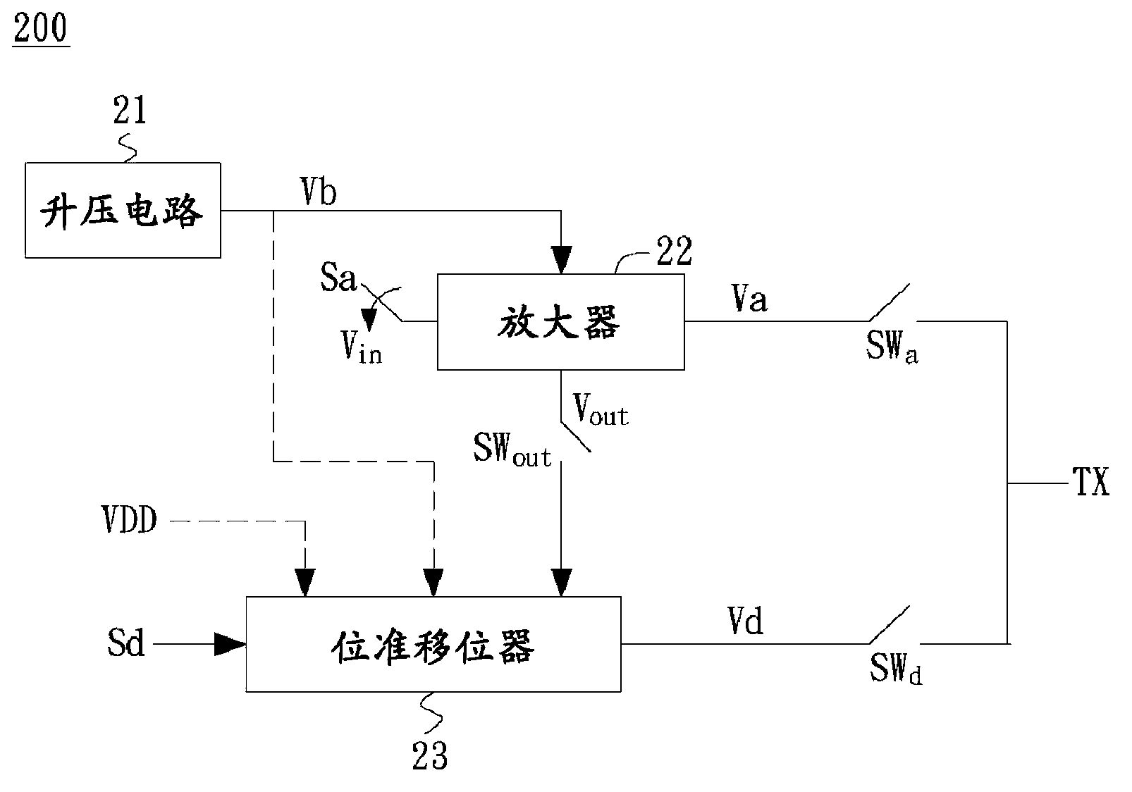
[0055] figure 2 It is a system block diagram of the driving signal generating system 200 of the embodiment of the present invention, which is applicable to the touch panel and used to provide the driving signal TX to the touch panel (not shown). The driving signal TX generates a sensing signal through the touch panel, which is used to determine whether the touch panel is touched and the position of the touch after signal processing.

[0056] In this example, if figure 2 As shown, a boost circuit 21 provides a power supply voltage Vb. The boost circuit 21 can ...


PUM


Abstract

The invention relates to a drive signal generation system. According to the drive signal generation system, a booster circuit provides a supply voltage, an amplifier provides analog waveform driving signals, a level shifter provides digital waveform drive signals, and a selecting unit selects the analog waveform drive signals as the drive signals in an analog waveform mode to a touch panel and selects the digital waveform drive signals as the drive signals in a digital waveform mode to the touch panel, wherein the booster circuit provides the supply voltage to the amplifier, and in the digital waveform mode, the amplifier generates and provides an output voltage for at least the last circuit of the level shifter as the power source.

Description

technical field [0001] The present invention relates to a touch panel, in particular to a driving signal generating system for providing a driving signal to the touch panel. Background technique [0002] A touch panel combined with a display screen can become a touch screen, which has been widely used as an input interface of an electronic device to detect a touch input in a display area. There are various touch technologies used in the touch panel, such as capacitive, resistive, or optical. Among them, the capacitive touch technology is the mainstream of the current touch technology. [0003] Capacitive touch panels are generally composed of horizontal electrodes and vertical electrodes, and the intersections of these electrodes define touch points. When the touch panel is operated, an electric field is formed between the two electrodes at the touch point. When a finger touches the panel, it will block part of the electric field, resulting in a decrease in the capacitance...

Claims


Application Information

Patent Timeline
Patent Type & Authority Applications(China)
IPC IPC(8): G06F3/041
Inventor 林柏全
Owner EGALAX EMPIA TECH INC
Learn More