Feedback signal detection method and pixel external analog domain compensation display system
A technology of feedback signal and detection method, applied in static indicators, instruments, etc., can solve the problems of aging OLED luminous efficiency reduction, OLED current reduction, uneven driving of driving circuits, etc.
- Summary
- Abstract
- Description
- Claims
- Application Information
AI Technical Summary
Problems solved by technology
Method used
Image
Examples
Embodiment 1
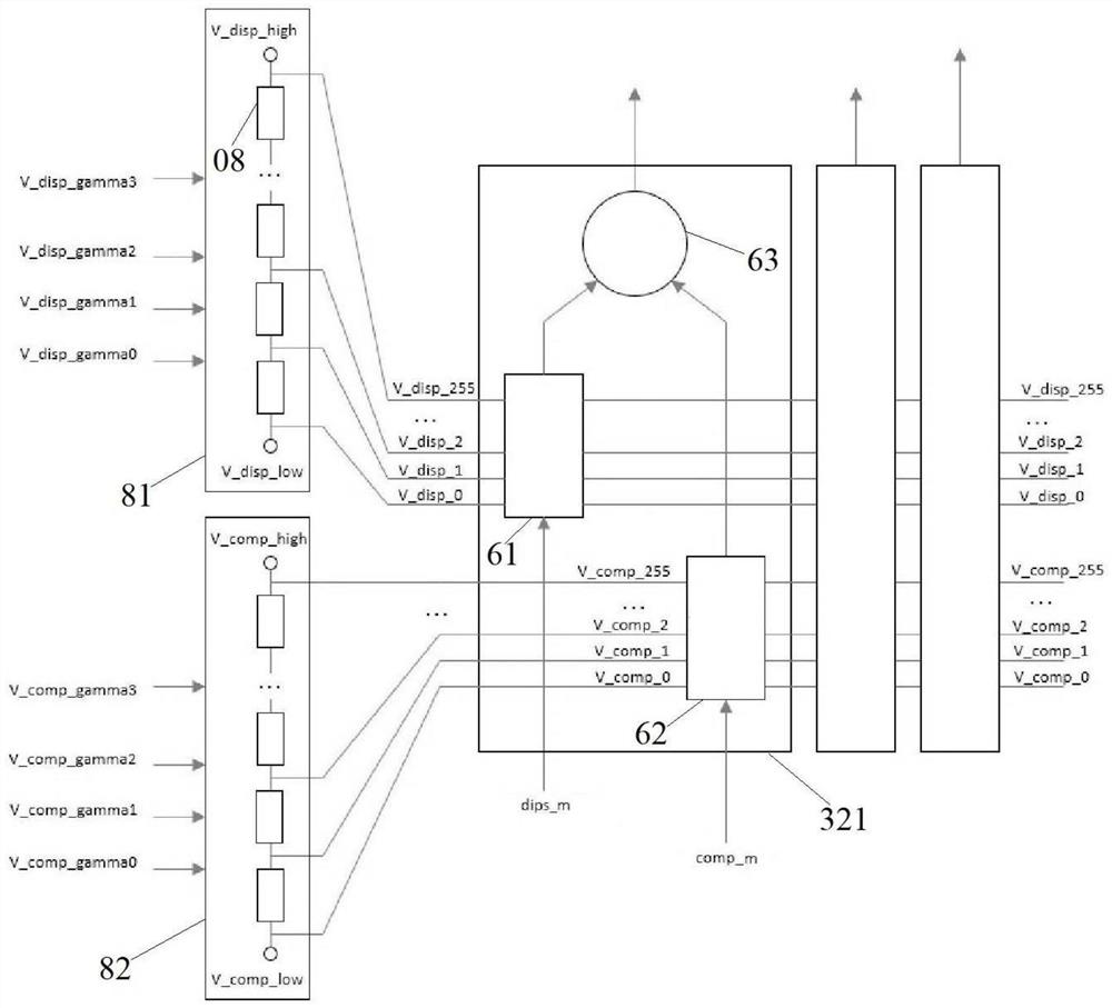
[0062] Figure 6 It is a schematic structural diagram of a traditional dual-DAC display system with external pixel compensation. There are M source drive modules 321 in the source driver, and each source drive module 321 includes 2 DACs, namely the first digital-to-analog converter 61 and the second digital-to-analog converter. 62 , the first digital-to-analog converter 61 and the second digital-to-analog converter 62 are respectively connected to the first shift-in circuit 34 and the second shift-in circuit 35 . During the display operation of the conventional dual DAC display system with extra-pixel compensation, the first digital-to-analog converter 61 is used to convert the 8-bit digital display signal disp_n_m, and the second digital-to-analog converter 62 is used to convert the 8-bit digital compensation signal comp_n_m. disp_n_m represents the display signal of the pixel unit in row n and column m, and comp_n_m represents the compensation signal of the pixel unit in row...
Embodiment 2
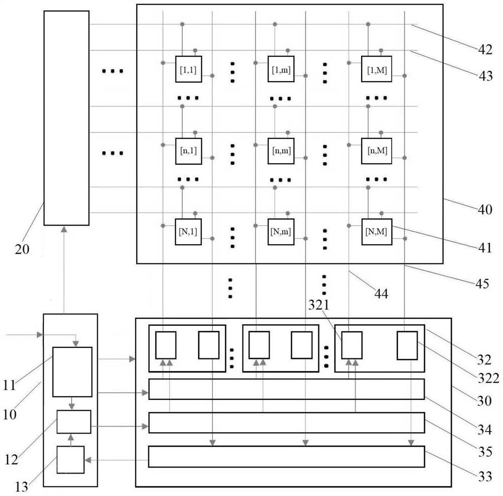
[0087] Such as figure 1 and Figure 8 As shown, this embodiment is in the Figure 6 An improvement is made on the basis of the traditional externally compensated display system shown, and the first digital-to-analog converter 61 and the second digital-to-analog converter 62 originally connected to the analog adder 63 are respectively connected to the display signal line 44 and the comparator 72 , the display system of the feedback signal detection method in this embodiment adopts Figure 4 The pixel unit shown; in the source driving module 321 of the mth column, the first digital-to-analog converter 61 is connected to the pixel unit 41 of the mth column of the driving channel through the display signal line 44 . The analog adder 63 in the source driver module 321 is idle. (In addition, another design is that the left input port of the adder is still connected to the output of 61, and the right input port is connected to 0V voltage, so that the output voltage of the adder is...
PUM
 Abstract
Description
Claims
Application Information
 - R&D
- Intellectual Property
- Life Sciences
- Materials
- Tech Scout
- Unparalleled Data Quality
- Higher Quality Content
- 60% Fewer Hallucinations
Browse by: Latest US Patents, China's latest patents, Technical Efficacy Thesaurus, Application Domain, Technology Topic, Popular Technical Reports.
© 2025 PatSnap. All rights reserved.Legal|Privacy policy|Modern Slavery Act Transparency Statement|Sitemap|About US| Contact US: help@patsnap.com


