An electronic horn driven by constant power and its realization method

An electronic horn and constant power technology, which is applied in the direction of sounding equipment and instruments, can solve the problems of inability to achieve accurate control, failure to eliminate failure modes, and inability to accurately control drive power, etc., to achieve the effect of eliminating speaker noise and shortening the life of the speaker

Active Publication Date: 2017-06-27
万喻
View PDF5 Cites 0 Cited by
  • Summary
  • Abstract
  • Description
  • Claims
  • Application Information

AI Technical Summary

Problems solved by technology

Although some people use constant current source driving or use analog devices to reduce the driving pulse width to reduce the current, but because of the inability to accurately control the driving power, the occurrence of such failure modes cannot be eliminated.
[0003] For example, the electric horn driven by a constant current source has a constant current of 4A. When the electric horn works at 9V, its power is 36W, at 13V, its power is 52W, and at 16V, its power is 64W. This method Although better than the common method without control, it is far from the requirement of accurate control to work with constant drive power

Method used


Image

  • An electronic horn driven by constant power and its realization method
  • An electronic horn driven by constant power and its realization method
  • An electronic horn driven by constant power and its realization method

Examples


Embodiment Construction

[0011] The technical solutions of the present invention will be described in further detail below with reference to the accompanying drawings and embodiments.

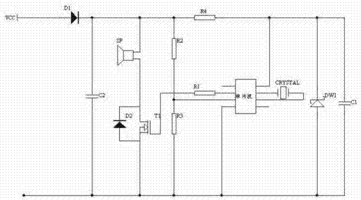
[0012] figure 1 It is a circuit diagram of an electronic horn driven by constant power according to an embodiment of the present invention.

[0013] like figure 1 As shown, the circuit diagram of this embodiment includes a power supply part, a power amplification part, a horn sound signal generation part and a supply voltage detection part.

[0014] The power supply part includes a series voltage stabilizing circuit composed of an anti-reverse polarity diode D1, a current limiting resistor R4, and a voltage stabilizing diode DW1. The anode of the anti-reverse polarity diode D1 is connected to the positive terminal VCC of the power supply, and the cathode is connected to the current limiting resistor R4. The capacitor C1 is connected in parallel with the Zener diode DW1, and then connected between the negative termin...


PUM


Abstract

The present invention relates to an electronic horn driven by constant power and its realization method. The method comprises: detecting the current power supply voltage of the electronic horn to obtain the current power supply voltage value; The power value calculates the pulse width of the electronic horn drive signal under the current supply voltage, and the pulse width of the electronic horn drive signal under the current supply voltage meets the condition of driving the electronic horn with a preset constant drive power; pulse the drive signal of the electronic horn Width modulation, modulating the driving signal to the pulse width under the current supply voltage; using the pulse width modulated driving signal to drive the electronic horn to sound. The present invention automatically changes the pulse width of the horn driving signal through calculation when the power supply voltage of the horn changes, ensures that the horn works accurately at the rated power, solves the problem that the sound pressure level of the horn is affected by the power supply voltage, and eliminates the noise of the horn and the shortened life of the horn caused by iron striking disadvantages.

Description

technical field [0001] The invention relates to the field of electronic horns for vehicles and ships, in particular to an electronic horn driven by constant power and a realization method thereof. Background technique [0002] Generally, electric horns for motor vehicles and ships, no matter they are mechanical or electronic, the driving power of the horn itself changes greatly due to the influence of the power supply voltage. For example, electric speakers are required to work at a voltage of 9-16 volts. According to the standard voltage of 13V and the operating current of 4A, the power of the speaker will vary greatly within the range of 25W-79W. This has a great impact on the sound effect of the speaker and the life of the speaker. It is very easy to cause a large attenuation of the sound level of the speaker under low voltage, and the collision between the moving iron core and the fixed iron core of the electromagnet driving the diaphragm to produce sound under high volt...

Claims


Application Information

Patent Timeline
Patent Type & Authority Patents(China)
IPC IPC(8): G10K9/12
Inventor 万喻
Owner 万喻
Why Eureka
Try Eureka