Check patentability & draft patents in minutes with Patsnap Eureka AI!

overcurrent protection element

一种保护元件、过电流的技术,应用在电流响应的电阻器、具有正温度系数的电阻器等方向,达到提升生产速度的效果

Active Publication Date: 2016-03-16
POLYTRONICS TECH CORP
View PDF6 Cites 0 Cited by
  • Summary
  • Abstract
  • Description
  • Claims
  • Application Information

AI Technical Summary

Problems solved by technology

However, the larger semicircular hole design will cause problems in the production process as described below

Method used


Image

  • overcurrent protection element
  • overcurrent protection element
  • overcurrent protection element

Examples


Embodiment Construction

[0051] In order to make the above-mentioned and other technical contents, features and advantages of the present invention more obvious and understandable, the relevant embodiments are specifically listed below, and are described in detail as follows in conjunction with the accompanying drawings:

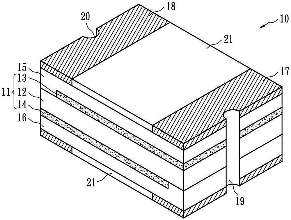
[0052] Figure 4A It is a three-dimensional structural diagram of an overcurrent protection element according to an embodiment of the present invention. The overcurrent protection element 40 is approximately a rectangular parallelepiped with opposite upper surfaces, lower surfaces and four side surfaces. The four side surfaces connect the upper surface and the lower surface, and adjacent side surfaces form four corners. The overcurrent protection element 40 includes: a PTC material layer 41, a first conductive layer 42, a second conductive layer 43, a first insulating layer 44, a second insulating layer 45, a first electrode layer 46, a second electrode layer 47 and four A conduct...


PUM


Abstract

An overcurrent protection element includes: a PTC material layer, a first conductive layer, a second conductive layer, a first electrode layer, a second electrode layer and four conductive through holes. The first and second conductive layers physically contact the first surface and the second surface of the PTC material layer respectively. The first electrode layer includes a pair of first metal foils, which are electrically connected to the first conductive layer and electrically isolated from the second conductive layer. The second electrode layer includes a pair of second metal foils, which are electrically connected to the second conductive layer and electrically isolated from the first conductive layer. Four conductive vias are formed at four corners formed by adjacent side surfaces, two of which are connected to the pair of first metal foils and the first conductive layer, and the other two are connected to the pair of second metal foils and the second conductive layer. The sum of the cross-sectional areas of the four conductive via holes accounts for 7%-20% of the form factor area of ​​the overcurrent protection element. The overcurrent protection element of the present invention can meet the demands of the miniaturization trend of elements.

Description

technical field [0001] The invention relates to an overcurrent protection element, in particular to a surface-adhesive overcurrent protection element. Background technique [0002] Overcurrent protection elements are used to protect circuits from being damaged by overheating or excessive current flow. An overcurrent protection device usually includes two electrodes and a resistive material between the two electrodes. This resistance material has a positive temperature coefficient (PositiveTemperatureCoefficient; PTC) characteristic, that is, it has a low resistance value at room temperature, and when the temperature rises to a critical temperature or an excessive current is generated in the circuit, its resistance value can immediately jump thousands of times, thereby suppressing the passage of excessive current to achieve the purpose of circuit protection. When the temperature drops back to room temperature or there is no overcurrent on the circuit, the overcurrent protec...

Claims


Application Information

Patent Timeline
Patent Type & Authority Patents(China)
IPC IPC(8): H01C7/02H01C7/13
CPCH01C7/02H01C7/13
Inventor 曾郡腾王绍裘
Owner POLYTRONICS TECH CORP
Features
  • R&D
  • Intellectual Property
  • Life Sciences
  • Materials
  • Tech Scout
  • Unparalleled Data Quality
  • Higher Quality Content
  • 60% Fewer Hallucinations
Learn More