LED material strap with identification structure

A material tape and lead frame technology, applied in electrical components, circuits, semiconductor devices, etc., can solve the problems of mold cost, process time-consuming, product cost increase, etc.

Inactive Publication Date: 2014-02-12
I-CHIUN PRECISION IND CO LTD +1
View PDF3 Cites 7 Cited by
  • Summary
  • Abstract
  • Description
  • Claims
  • Application Information

AI Technical Summary

Problems solved by technology

[0003] However, in the manufacturing process of the above-mentioned light-emitting diode, because the chip of the light-emitting diode must be arranged on the first pin 21a, and the second pin 22a is used for connecting and bonding wires, therefore, the lead frame 10a must have a certain The direction is placed in the mold to place the chip on the correct pins, and the subsequent wire bonding and packaging process
[0004] The conventional method for judging the directionality of the

Method used


Image

  • LED material strap with identification structure
  • LED material strap with identification structure
  • LED material strap with identification structure

Examples


Embodiment Construction

[0033] The detailed description and technical content of the present invention are described below with the accompanying drawings, but the attached drawings are only for reference and illustration, and are not used to limit the present invention.

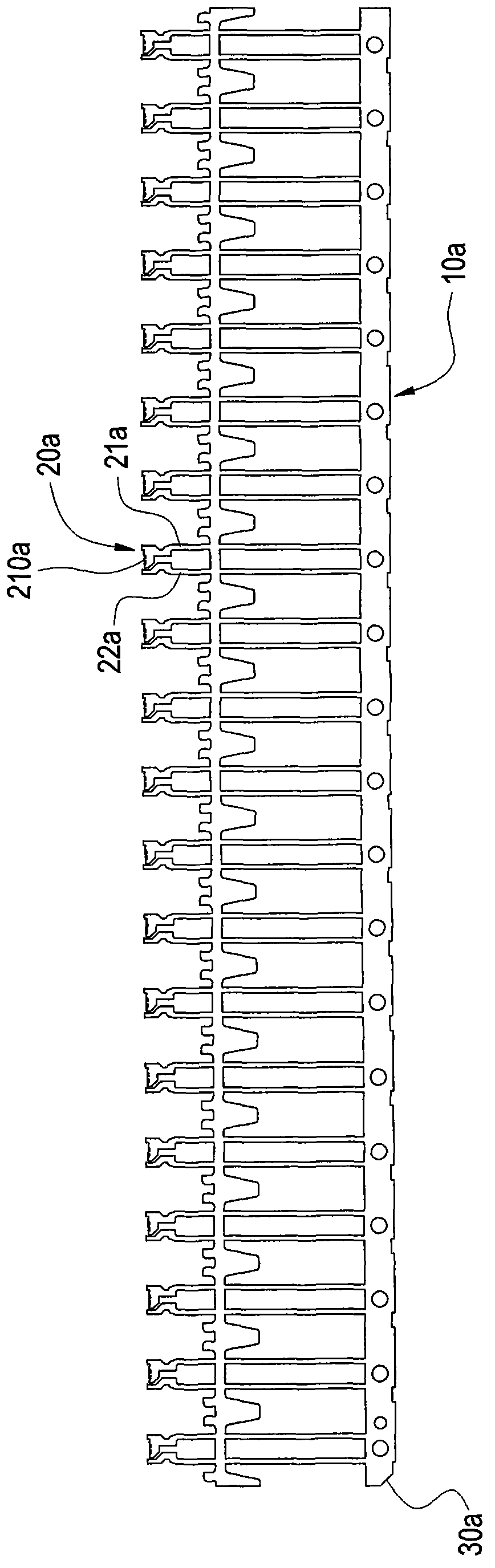
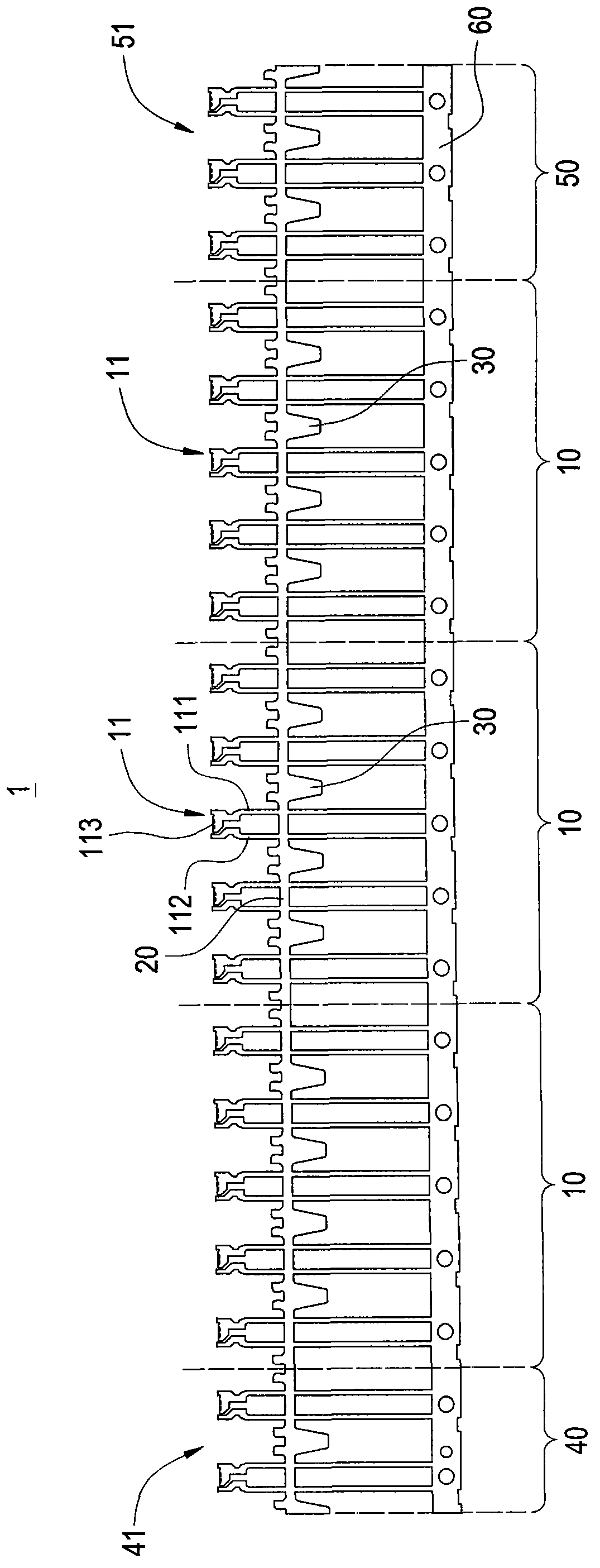
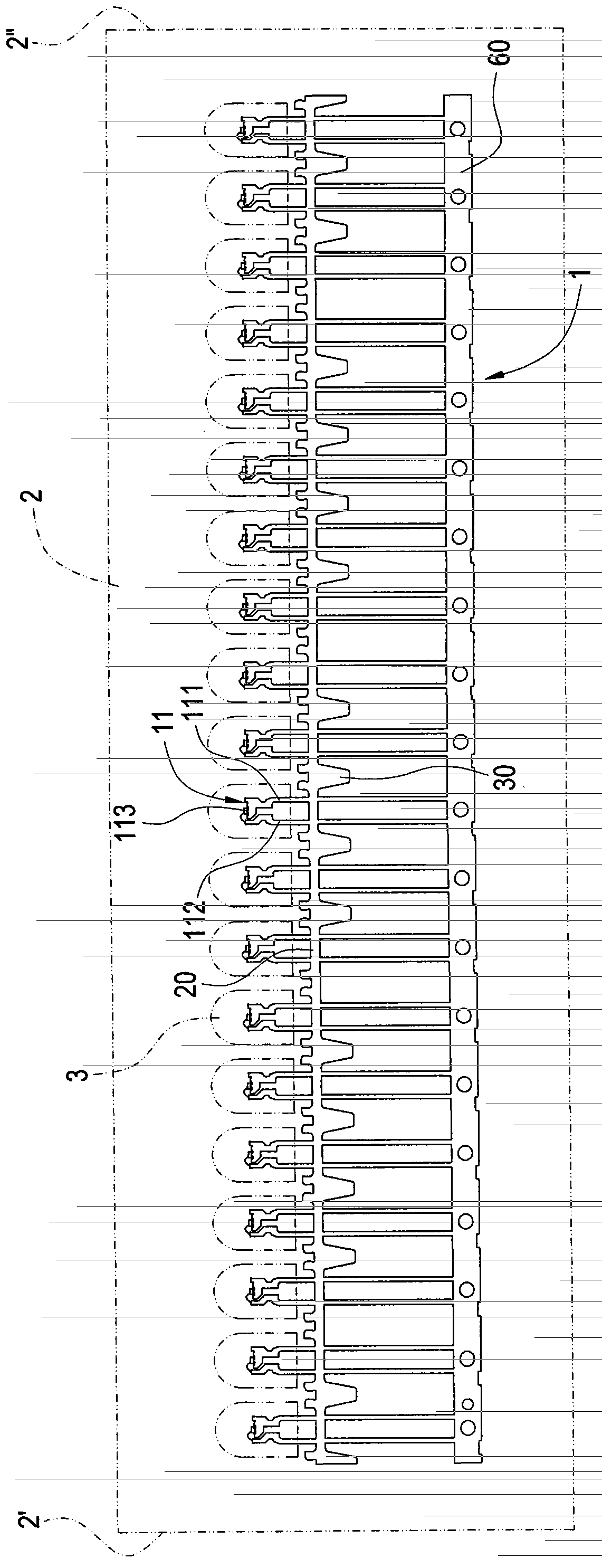
[0034] Please refer to figure 2 , is a schematic plan view of the LED strip with identification structure of the present invention, the LED strip 1 includes a plurality of lead frame groups 10, at least one main connecting section 20, a plurality of clamping pieces 30, and a first zero-distortion lead frame 40 And the second zero-distortion lead frame 50.

[0035] These lead frame groups 10 are arranged in a straight line, and each lead frame group 10 includes a certain number of bracket units 11; It then includes five bracket units 11 . Each of the bracket units 11 includes a first pin 111 and a second pin 112 arranged at intervals. The first pin 111 is formed with a concave cup 113 for a LED chip.

[0036] The main connecting ...


PUM


Abstract

The invention discloses an LED material strap with an identification structure. The LED material strap comprises a plurality of lead frame sets, main joint sections, a plurality of clamping sheets, first support units and second support units, the lead frame sets are connected in an equal-distance mode and arranged linearly, each lead frame set comprises support units in a certain number, the main joint sections are connected with the support units in series and are in extending connection with the adjacent lead frame sets, the clamping sheets are arranged between the adjacent support units and protrude and extend out of one lateral sides of the main joint sections, the first support units and the second support units are arranged on two outer sides of the lead frame sets respectively, the number of the first support units is not equal to that of the second support units, and the total of the number of the first support units and the number of the second support units is equal to the number of the support units included in each lead frame set. The direction of the LED material strap is judged through the structure.

Description

technical field [0001] The invention relates to an LED material strip, in particular to an LED material strip with an identification structure. Background technique [0002] Please refer to figure 1 As shown, the vertical light-emitting diode support structure is provided with a plurality of equidistantly connected support units 20a on a lead frame 10a, and each support unit 20a is respectively provided with two opposite first pins 21a and second pins. pin 22a, and a bowl-shaped recess 210a is formed on the upper end of the first pin 21a for carrying and fixing a chip (solid crystal, Die bond). In addition, the upper end of the second pin 22a has a contact point for power supply Connect a wire; Then, connect the chip on the first pin 21a and the contact point on the second pin 22a by welding (connecting wire, Wiring), after the electrical connection is completed, pass through the packaging material (such as Epoxy resin) to be packaged and packaged, and operations such as c...

Claims


Application Information

Patent Timeline
IPC IPC(8): H01L33/48
CPCH01L22/20H01L33/62
Inventor 蔡敏成
Owner I-CHIUN PRECISION IND CO LTD
Why Eureka
Try Eureka