Power distribution cabinet

A technology for power distribution cabinets and cabinets, applied in the field of power distribution cabinets for EMUs, can solve the problems of large deformation of the cabinets, residual stress, poor aesthetics, etc. Effect

Active Publication Date: 2014-02-12
CRRC QINGDAO SIFANG CO LTD
View PDF5 Cites 0 Cited by
  • Summary
  • Abstract
  • Description
  • Claims
  • Application Information

AI Technical Summary

Problems solved by technology

[0002] The CRH2 type EMU power distribution cabinet is mainly processed by welding process. This type of power distribution cabinet has problems such as large deformation of the cabinet, prone to welding defects, prone to residual stress, poor aesthetics, incapable of modular assembly, and poor versatility.
With the improvement of the overall performance of high-speed EMUs, the welded structure power distribution cabinet can no longer meet the development needs of CRH2 EMUs, and has seriously mismatched with the advanced CRH2 EMU technology.

Method used


Image

  • Power distribution cabinet
  • Power distribution cabinet
  • Power distribution cabinet

Examples


Embodiment 1

[0024] A power distribution cabinet of the present invention includes a main skeleton structure, a transition skeleton structure, and an auxiliary skeleton structure, and the main skeleton structure, the transition skeleton structure and the auxiliary skeleton structure are riveted with rivets.

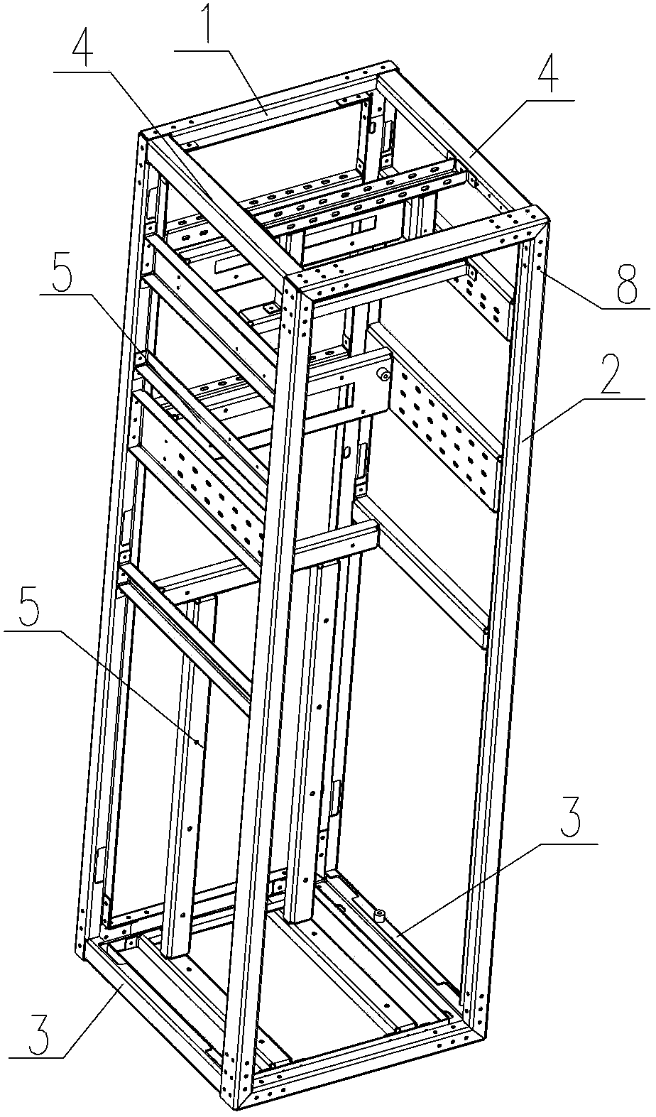
[0025] Such as figure 1 As shown, the main skeleton structure plays the main supporting role, including the front skeleton frame 2 located at the front side of the power distribution cabinet, and the rear skeleton frame 1 located at the rear side of the power distribution cabinet. The front skeleton frame 2 is mouth-shaped, and the rear skeleton frame 1 is also mouth-shaped. . The front skeleton frame 2 and the rear skeleton frame 1 are spliced ​​by four frames, which makes the assembly easier and more convenient, and can improve the versatility of the overall frame structure of the power distribution cabinet.

[0026] The transition skeleton structure acts as a connection, consistin...

Embodiment 2

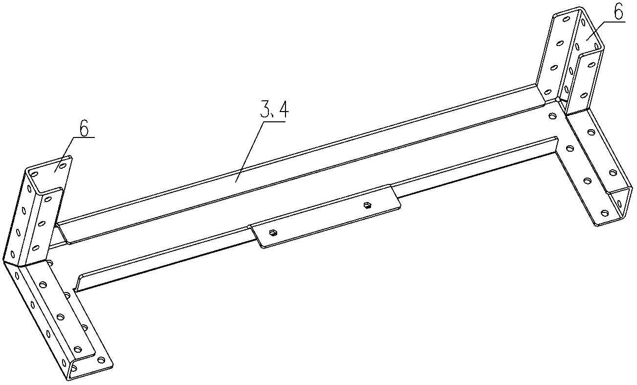
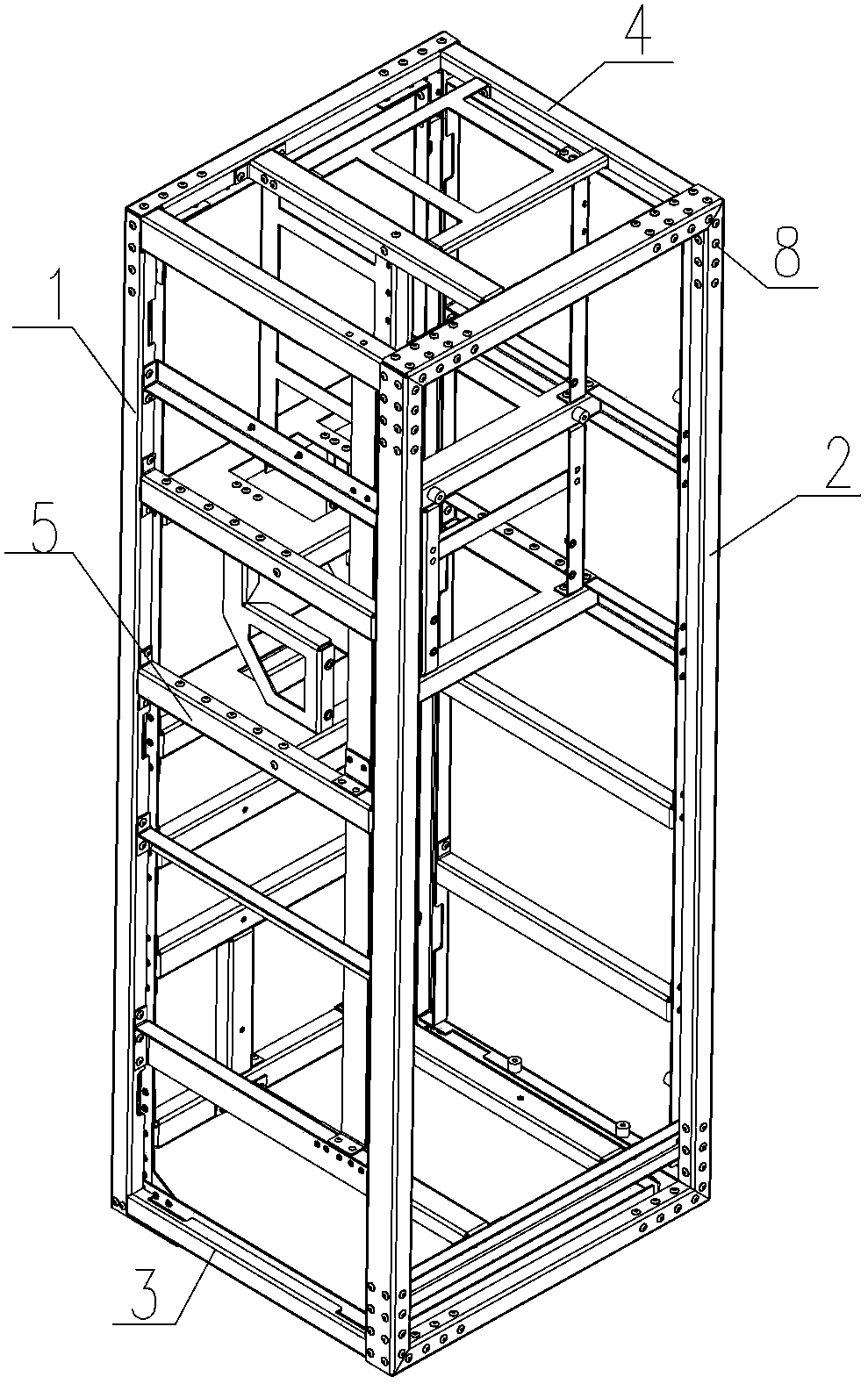
[0031] Such as image 3 As shown, for wiring or structural needs, the rear skeleton frame 1 adopts a door-shaped structure, the rear skeleton frame 1 has no bottom frame, and the upper transition skeleton 4 is as figure 2 Both ends shown are provided with corner structures 6, and the lower transition frame 3 is as Figure 4 As shown, the corner structure 6 is only provided at one end, and the corner structure 6 is not provided at the other end.

[0032] The two upper transition frames 4 and the two lower transition frames 3 are riveted and spliced ​​together by riveting the four frames of the front frame frame 2 and the rear frame frame 1 by means of corner structures 6 or directly fixed at the ends, and then forming a A mouth-shaped front skeleton frame 2 and a door-shaped rear skeleton frame 1.


PUM


Abstract

The invention provides a power distribution cabinet which is simple in structure and capable of being assembled in a modularization mode and is not deformed. A cabinet body of the power distribution cabinet comprises main frame structures, transitional frame structures and auxiliary frame structures, wherein the main frame structures play a role of supporting, the transitional frame structures are used for connecting the main frame structures, the auxiliary frame structures are fixedly connected with the main frame structures and/or the transitional frame structures and are used for supporting and wiring in an auxiliary mode, and the main frame structures, the transitional frame structures and the auxiliary frame structures are connected in a riveting mode.

Description

technical field [0001] The invention relates to a novel power distribution cabinet body, in particular to a power distribution cabinet for an EMU in a high-speed railway. Background technique [0002] The CRH2 type EMU power distribution cabinet is mainly processed by welding process. This type of power distribution cabinet has problems such as large deformation of the cabinet, prone to welding defects, prone to residual stress, poor aesthetics, incapable of modular assembly, and poor versatility. With the improvement of the overall performance of high-speed EMUs, the welded structure power distribution cabinet can no longer meet the development needs of CRH2 EMUs, and has seriously mismatched with the advanced CRH2 EMUs technology. Contents of the invention [0003] The main purpose of the present invention is to solve the above-mentioned problems and deficiencies, to provide a power distribution cabinet structure that is simple in structure, without deformation, and can ...

Claims


Application Information

Patent Timeline
Patent Type & Authority Applications(China)
IPC IPC(8): H02B1/26
Inventor 王洪波吴冬华邓学寿
Owner CRRC QINGDAO SIFANG CO LTD
Why Eureka
Try Eureka