
Dual-mode SVPWM overmodulation method

A modulation method and over-modulation technology, applied in the field of electric power, can solve problems such as unfavorable algorithm engineering implementation, and achieve the effects of good output voltage continuity, easy engineering implementation, and high control accuracy

Active Publication Date: 2014-02-12
HUAZHONG UNIV OF SCI & TECH
View PDF1 Cites 21 Cited by
  • Summary
  • Abstract
  • Description
  • Claims
  • Application Information

AI Technical Summary

Problems solved by technology

[0025] Therefore, when the desired output voltage vector phase angle is , in engineering implementation, it is necessary to calculate the phase angle of the expected output voltage vector in each switching cycle, and then modify the phase angle through formula (7) to obtain a new output voltage vector, and then calculate the vector action time t according to the new voltage vector 1 and t 2 , this mild modification of the output voltage vector ensures high control accuracy, but the resulting large number of trigonometric and inverse trigonometric calculations is not conducive to the engineering implementation of the algorithm

Method used


Image

  • Dual-mode SVPWM overmodulation method
  • Dual-mode SVPWM overmodulation method
  • Dual-mode SVPWM overmodulation method

Examples


Embodiment Construction

[0071] In order to make the object, technical solution and advantages of the present invention clearer, the present invention will be further described in detail below in conjunction with the accompanying drawings and embodiments. It should be understood that the specific embodiments described here are only used to explain the present invention, not to limit the present invention. In addition, the technical features involved in the various embodiments of the present invention described below can be combined with each other as long as they do not constitute a conflict with each other.

[0072] The technical scheme adopted in the present invention is:

[0073] According to the modulation coefficient, the SVPWM modulation area is divided into linear modulation area, over-modulation 1 area and over-modulation 2 area.

[0074] In overmodulation zone 1 (0.9069<MI≤0.9517): continue to use the classic dual-mode control method.

[0075] In overmodulation zone 2 (0.9517h , the actual ...


PUM


Abstract

The invention discloses a dual-mode SVPWM overmodulation method. The method comprises the steps that a modulation area is divided into a linear modulation area, a first overmodulation area and a second overmodulation area according to a modulation factor, wherein when an MI is larger than 0 and smaller than 0.9069, it is the linear modulation area, when the MI is larger than 0.9069 and smaller than or equal to 0.9517, it is the first overmodulation area, when the MI is larger than 0.9517 and smaller than or equal to 1, it is the second overmodulation area, and the MI is the modulation factor; a traditional SVPWM modulation method is used in the linear modulation area; a reference angle is used for controlling the compensation of an actual output voltage vector in the first overmodulation area; the mode that the actual output voltage vector hops at the position where a phase angle is a keep angle is used in the second overmodulation area, and the mode that an expected output voltage vector is followed by hopping is used for controlling the track of the output voltage vector. Compared with a traditional dual-mode control method, the dual-mode SVPWM overmodulation method is simple in algorithm, avoids complex operations, and is prone to engineering realization. Meanwhile, compared with a single-mode control method, the dual-mode SVPWM overmodulation method is high in control precision, and good in output voltage continuity.

Description

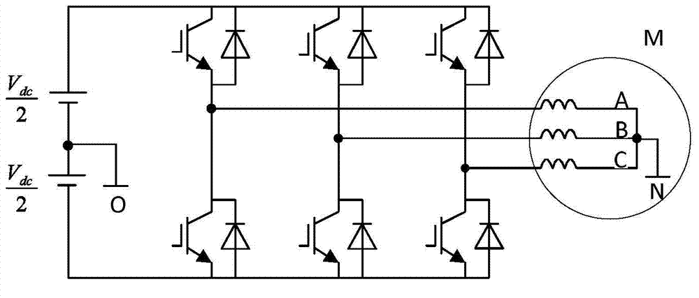
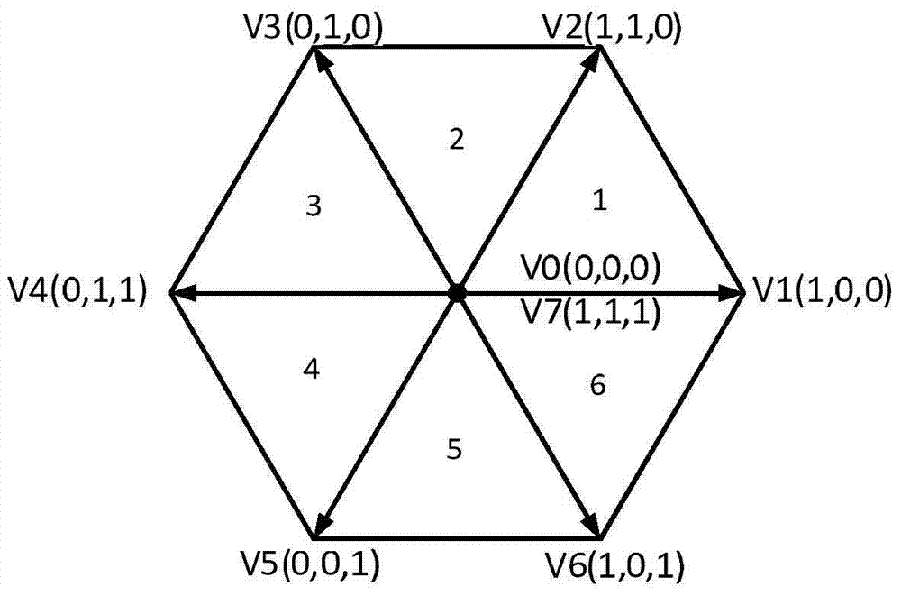
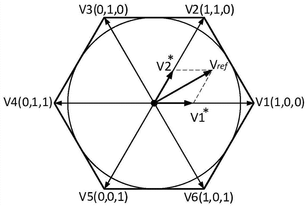
technical field [0001] The invention belongs to the technical field of electric power, and more specifically relates to a dual-mode SVPWM overmodulation method. Background technique [0002] SVPWM (Space Vector PWM, Space Vector Pulse Width Modulation) is an inverter modulation technology that uses different voltage vectors alternately to achieve motor flux trajectory control. attached figure 1 The PWM (Pulse Width Modulation, Pulse Width Modulation) inverter shown has eight working states, corresponding to eight basic space vectors, of which six effective working vectors V1~V6, whose amplitude is DC voltage difference in space The other two are zero vectors V0 and V7. The six effective working vectors divide the space voltage vector into six symmetrical sectors, and each sector corresponds to as attached figure 2 shown. [0003] Define Modulation Factor (where V ref is the desired output voltage vector, V dc is the DC bus voltage), when the desired output volt...

Claims


Application Information

Patent Timeline
Patent Type & Authority Applications(China)
IPC IPC(8): H02M7/48
Inventor 宋宝唐小琦宛世源陈天航夏亮黄金飞唐玉枝陈德
Owner HUAZHONG UNIV OF SCI & TECH
Learn More