Multi-level voltage source current converter and control method thereof

A technology of voltage source converter and control method, which is applied in the direction of converting AC power input to DC power output, electrical components, emergency protection circuit devices, etc. Safety, IGBT loss and other issues, to achieve the effect of reducing the number of thyristors, low harmonic content, simple and compact structure

Inactive Publication Date: 2014-02-12
NR ELECTRIC CO LTD +1
View PDF6 Cites 21 Cited by
  • Summary
  • Abstract
  • Description
  • Claims
  • Application Information

AI Technical Summary

Problems solved by technology

[0004] For the voltage source converters of the above three topologies, when the DC side fails, the AC side will feed a large fault current through the diode connected in parallel with the switching device. 40~60ms), the circuit breaker on the AC side is cut off, which seriously threatens the safety of the converter, and therefore requires an additional protection circuit
For multi-terminal DC power grids, the DC power transmission system using these topologies must jump off the AC side switches of all converters to clear the fault when the DC side is faulty, which has a serious impact on the operation of the power grid.
[0005] At present, the voltage source converter mainly uses IGBT as the switching device. IGBT has large loss, low withstand voltage and high cost, which restricts the application and development of voltage source DC transmission to a certain extent.

Method used


Image

  • Multi-level voltage source current converter and control method thereof
  • Multi-level voltage source current converter and control method thereof
  • Multi-level voltage source current converter and control method thereof

Examples


Embodiment Construction

[0028] The technical solutions and beneficial effects of the present invention will be described in detail below in conjunction with the accompanying drawings.

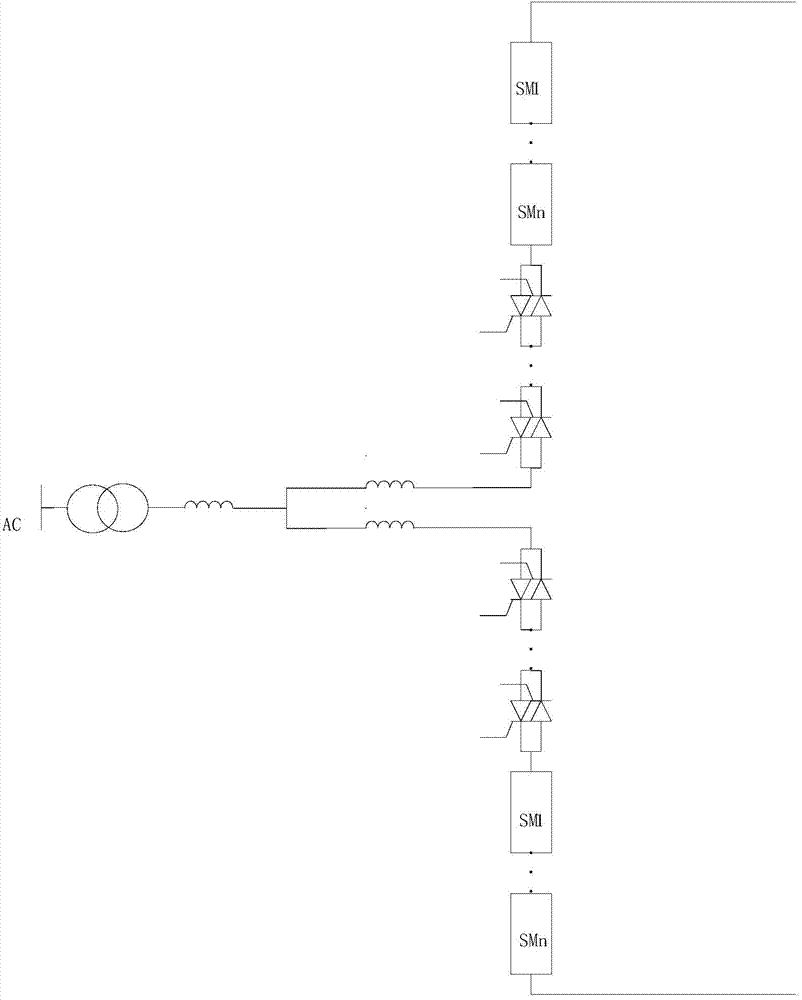
[0029] Such as figure 1 As shown, the present invention provides a multi-level voltage source converter, including at least one phase unit, each phase unit includes an upper bridge arm, a lower bridge arm, and a converter reactor, and both the upper and lower bridge arms Including at least two sub-modules in series, a switch circuit and a bridge arm reactor, all sub-modules in the same bridge arm are connected in series in the same direction, and the polarities of the sub-modules connected to the switch circuit in the upper and lower bridge arms are opposite The upper and lower bridge arms are connected with one end of the bridge arm reactor in series, and are connected to the AC network through the converter reactor, and the other ends of the upper and lower bridge arms are respectively used as the first and second DC of...


PUM


Abstract

The invention discloses a multi-level voltage source current converter comprises at least one phase unit. Each phase unit comprises an upper bridge arm, a lower bridge arm and a current conversion electric reactor, wherein the upper bridge arm and the lower bridge arm respectively comprise at least two sub-modules, a switch loop and a bridge arm electric reactor all of which are sequentially connected in series; all sub-modules in the same bridge arm are connected in series in the same direction; the sub-modules, connected with the switch loop, in the upper bridge arm are opposite to the sub-modules, connected with the switch loop, in the lower bridge arm in polarity; one end, connected with the electric reactor in series, of the upper bridge arm and one end, connected with the electric reactor in series, of the lower bridge arm are connected and have access to an alternating current network through the current conversion electric reactor; the other end of the upper bridge arm and the other end of the lower bridge arm serve as a first direct current endpoint and a second direct current endpoint of the phase unit respectively to have access to a direct current network. Each switch loop comprises a plurality of anti-parallel thyristor pairs which are connected in series. The multi-level voltage source current converter is applied to flexible direct-current transmission and the like, and has the advantages of being small in number of the sub-modules, low in cost, small in consumption, capable of effectively blocking fault currents when the direct current side breaks down, and the like. The invention further discloses a control method of the multi-level voltage source current converter.

Description

Technical field [0001] The invention belongs to the field of flexible direct current transmission, and particularly relates to a multi-level voltage source converter and a control method thereof. Background technique [0002] Flexible DC transmission adopts voltage source converters, which can independently adjust the transmission of active and reactive power, improve the transmission capacity of the AC system, and easily form a multi-terminal DC transmission system, which can be used for grid connection of renewable energy generation, power supply in isolated cities, and AC system interconnection And other application fields, has obvious competitiveness. [0003] Currently, flexible DC transmission systems use more topological structures: two-level, three-level topologies and modular multi-level structures. Each bridge arm of the two-level structure of the voltage source converter is directly connected in series by multiple fully-controlled IGBT switches, and the voltage of the p...

Claims


Application Information

Patent Timeline
Patent Type & Authority Applications(China)
IPC IPC(8): H02M7/483H02M7/515H02H7/122
CPCH02M1/32H02M7/7575Y02E60/60H02M7/4835H02M1/0095
Inventor 冯亚东汪涛张茂强李乐乐
Owner NR ELECTRIC CO LTD
Why Eureka
Try Eureka