
Magnetic resonance imaging method and device

A magnetic resonance imaging and algorithm technology, which is applied in medical science, sensors, diagnostic recording/measurement, etc., can solve problems such as small data volume in overlapping sampling areas, reducing the accuracy and robustness of motion parameter estimation, and affecting the effect of motion artifact elimination. , to achieve the effect of eliminating motion artifacts

Active Publication Date: 2014-02-19
SHENZHEN MINDRAY BIO MEDICAL ELECTRONICS CO LTD
View PDF5 Cites 21 Cited by
  • Summary
  • Abstract
  • Description
  • Claims
  • Application Information

AI Technical Summary

Problems solved by technology

The PROPELLER method estimates the motion information of the examinee during the acquisition process by using the data in the overlapping sampling area of ​​the K-space center, thereby realizing motion compensation for the K-space strip; however, the traditional PROPELLER reconstruction algorithm cannot be too long because the echo chain cannot That is, the number of lines contained in a single K-space strip is limited, resulting in too small data volume in the overlapping sampling area, which inevitably reduces the accuracy and robustness of motion parameter estimation, and ultimately affects the elimination effect of motion artifacts

Method used


Image

  • Magnetic resonance imaging method and device
  • Magnetic resonance imaging method and device
  • Magnetic resonance imaging method and device

Examples


Embodiment 1

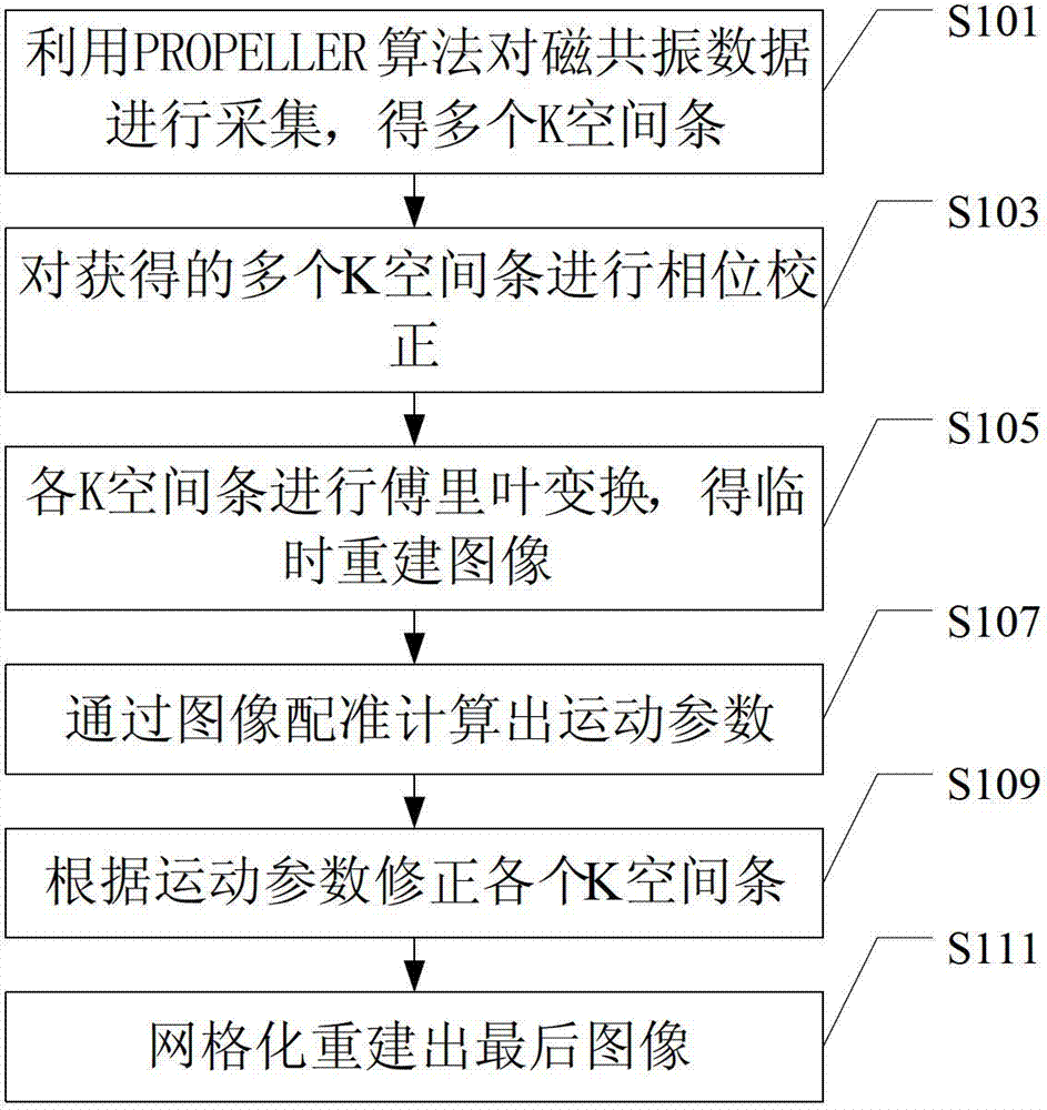
[0015] Such as figure 1 As shown, the magnetic resonance imaging method of this embodiment includes the following steps S101~S111:

[0016] Step S101, the data collection step, using the PROPELLER algorithm to collect magnetic resonance data to obtain multiple K-space strips;

[0017] K space refers to the frequency data space composed of magnetic resonance data collected after phase encoding and frequency encoding, that is, the frequency space composed of magnetic resonance sampling data, that is, the frequency domain space corresponding to the magnetic resonance image.

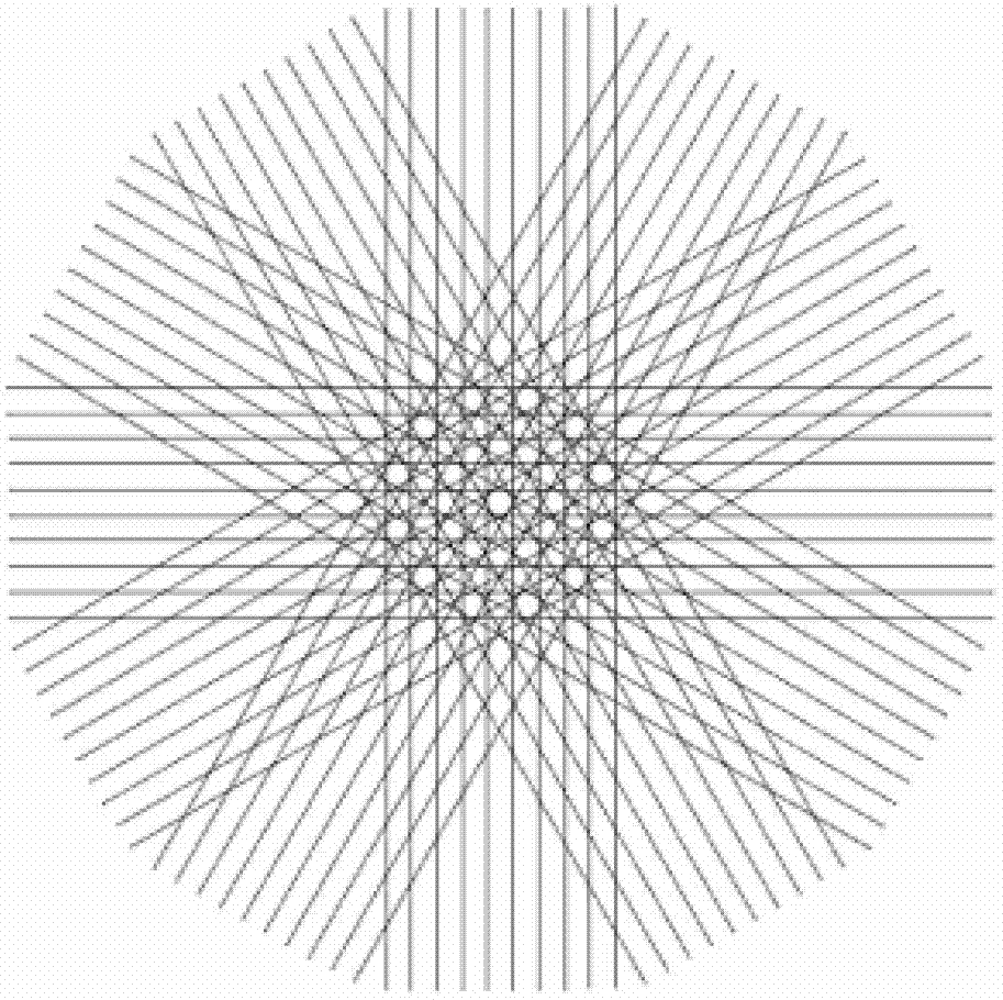
[0018] The magnetic resonance data can be sampled by the commonly used PROPELLER algorithm. For example, firstly, a group of K-space lines near the center of K-space is collected by conventional methods such as FSE (fast spin echo) sequence, single-shot echo-planar sequence, etc., assuming For L strips, a K-space strip is obtained, and then the data of the next K-space strip is collected in the same way eve...

Embodiment 2

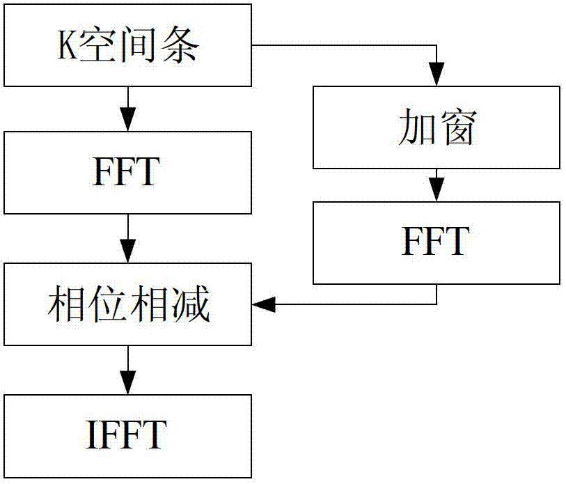
[0060] Such as Figure 4 As shown, the magnetic resonance imaging method of this embodiment includes steps S401~S411, wherein steps S401, S403, S405, S407, S409, and S411 are similar to steps S101, S103, S105, S107, S109, and S111 of Embodiment 1, respectively, No longer. The difference between this embodiment and Embodiment 1 is that step S406 is added after step S405 and before step S407 to filter the temporarily reconstructed image.

[0061] Due to the lack of many high-frequency signals, the image reconstructed in step S405 is generally blurred, and because the phase encoding direction is truncated, the image has obvious Gibbs artifacts, so it is necessary to further filter the image (that is, step S406 ). In this embodiment, a two-dimensional Gaussian window function is used for filtering, and the formula is as follows:

[0062] G ( k x , k y ...

Embodiment 3

[0066] Such as image 3 As shown, this embodiment proposes a magnetic resonance imaging device corresponding to the magnetic resonance imaging method of embodiment 1 or embodiment 2, including:

[0067] The data collection module is used to collect the magnetic resonance data by using the PROPELLER algorithm to obtain a plurality of K-space bars;

[0068] A phase correction module, configured to perform phase correction on the obtained multiple K-space strips, so that the center position of each K-space strip coincides with the center of K-space;

[0069] The temporary reconstruction module is used to perform Fourier transform on the corrected K-space strips to obtain temporary reconstructed images respectively corresponding to each K-space strip; or, the temporary reconstruction module is used to perform Fourier transform to obtain temporary reconstructed images respectively corresponding to each K-space strip, and also to filter the temporary reconstructed image after obtai...


PUM


Abstract

The invention discloses a magnetic resonance imaging method and device. The magnetic resonance imaging method comprises collecting through a PROPELLER (Periodically Rotated Overlapping Parallel Lines with Enhanced Reconstruction) algorithm to obtain a plurality of K-space bars; performing Fourier transformation on the K-space bars to obtain temporary reconstructed images which are corresponding to the K-space bars respectively; enabling the temporary reconstructed image which is corresponding to one K-space bar to be served as a reference image, enabling the temporary reconstructed images which are corresponding to other temporary reconstructed images to be served as images to be performed registration and working out optimal motion parameters of the images to be performed registration relative to the reference image through image registration; correcting the K-space bars which are obtained before the temporary reconstructed images according to obtained optimal motion parameters; rearranging the corrected K-space bars, performing the Fourier transformation on a rearranged result and obtaining imaging images. The magnetic resonance imaging method is less influenced by acquisition parameters such as the echo train length and provides possibilities for eliminating motion artifacts due to the fact that estimation of motion parameters is performed based on registration of image fields.

Description

technical field [0001] The invention relates to the field of magnetic resonance technology, in particular to a magnetic resonance imaging method and device. Background technique [0002] Magnetic Resonance Imaging (MRI, Magnetic Resonance Imaging) has been widely used clinically due to the advantages of non-invasive and multi-parameter imaging, and is one of the important inspection methods of current clinical medical imaging. However, due to the long data acquisition time of magnetic resonance imaging, the imaging process is easily disturbed by motion, so that motion artifacts appear in the imaging image, which may affect the doctor's diagnosis. Therefore, how to effectively overcome the influence of motion on imaging has always been one of the hot spots and technical problems in MRI research. [0003] Currently, the method of PROPELLER, Periodically Rotated Overlapping Parallel Lines with Enhanced Reconstruction (PROPELLER, Periodically Rotated Overlapping Parallel Lines ...

Claims


Application Information

Patent Timeline
Patent Type & Authority Applications(China)
IPC IPC(8): A61B5/055
Inventor 云天梁武文鹏邓晓云谢鹏程
Owner SHENZHEN MINDRAY BIO MEDICAL ELECTRONICS CO LTD
Learn More