Serration-type steel reinforcement cage machining jig frame and construction method thereof

A construction method and reinforcement cage technology, applied in the direction of wire rod processing, other household appliances, and wire manufacturing of ring nets, etc., can solve the problems of inability to form flow operations, uneven distribution of main reinforcement, slow construction progress, etc., and reduce construction work. The investment of personnel and equipment, the reduction of processing costs, and the effect of construction quality assurance

Active Publication Date: 2014-02-19
CCCC SHEC FOURTH ENG +1
View PDF11 Cites 6 Cited by
  • Summary
  • Abstract
  • Description
  • Claims
  • Application Information

AI Technical Summary

Problems solved by technology

[0005] 1. Since the existing tire frame is a semi-circular arc shape, the main reinforcement of the upper part of the steel cage cannot be positioned on the tire frame. It is necessary to manually use a steel tape measure to position the wires. The tire frame can only play a part of the role, resulting in the above part of the tire frame. The distribution of the main ribs is uneven, not straight, and the appearance quality is poor;
[0006] 2. Welders and steel bar binding workers are mixed together to work, which cannot form a flow operation, resulting in a slow construction progress;
[0007] 3. It consumes more labor force;
[0008] 4. Since the steel cage cannot rotate on the tire frame, some welds are upward welds, and the welding quality is poor;
[0009] 5. The tire frame under the steel cage must be hoisted by a crane, and the construction cost is high;
[0010] 6. The tire frame can only position some steel bars

Method used


Image

  • Serration-type steel reinforcement cage machining jig frame and construction method thereof
  • Serration-type steel reinforcement cage machining jig frame and construction method thereof
  • Serration-type steel reinforcement cage machining jig frame and construction method thereof

Examples


Embodiment Construction

[0033] The following non-limiting examples illustrate the invention.

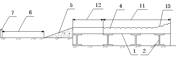
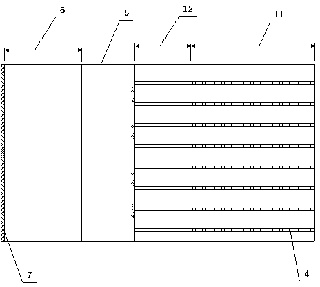
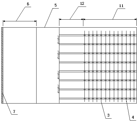
[0034] Such as Figures 1 to 3 As shown, a tire frame processed by a sawtooth steel cage includes several strip-shaped tire frames arranged side by side. The tire frame is composed of a tire frame body 1 and a bracket 2 supporting the tire frame body 1. The tire frame body 1 is A steel plate, the bracket 2 is made of section steel, the tire frame is divided into the main reinforcement welding and forming area 11 and the spiral reinforcement binding area 12 along its length direction, and the main reinforcement welding and forming area 11 is far away from the spiral reinforcement binding area 12, and the tail of one end is a circle Arc segment 13, its upper surface is raised in an arc, and the upper surface of arc segment 13 is a 45° arc; tire frames are arranged horizontally, and each tire frame is parallel to each other and the upper surface is even; the main rib welding and forming area 11 The surface is...


PUM


Abstract

The invention discloses a serration-type steel reinforcement cage machining jig frame, and belongs to the field of steel reinforcement cage machining. The jig frame is divided into a main rib welding and forming area and a spiral rib bonding area, wherein the tail portion of the main rib welding and forming area is an arc section, and the upper surface of the main rib welding and forming area is provided with a plurality of notches matched with intervals and diameters of main ribs at equal intervals. The construction method sequentially includes the following steps that the main ribs needing to be welded are placed in the notches of the main rib welding and forming area of each jig frame one by one, firstly, the main ribs on the arc section of each jig frame are welded and roll towards the spiral rib bonding area of the corresponding jig frame after welding, the main ribs sequentially roll, are sequentially welded and ultimately roll to the spiral rib bonding area, and spiral stirrups are bound. According to the jig frame and a construction method of the jig frame, all the main ribs of a machined steel reinforcement cage are evenly distributed, machining quality of the steel reinforcement cage is higher, function requirements can be met on the condition that the machining progress of the steel reinforcement cage is accelerated, construction operators and equipment investment are reduced, and machining cost of the steel reinforcement cage is reduced.

Description

technical field [0001] The invention belongs to the field of reinforcement cage processing and is suitable for processing various types of pile foundation reinforcement cages. Background technique [0002] 1) Traditional steel cage processing tire frame construction technology: [0003] Since the reinforcement cage member is cylindrical, it is composed of several main reinforcements at equal intervals, a plurality of positioning hoops distributed along the length direction of the main reinforcements and welded and fixed with each main reinforcement, and a spiral reinforcement connecting the main reinforcements in a circular ring. Control during construction The spacing and processing quality of the main bars of the steel cage are relatively difficult, so the steel cage processing frame is used in the process of forming the steel cage. The steel frame is used for positioning control to prevent uneven processing of the main bars of the steel cage and welding. A structure that...

Claims


Application Information

Patent Timeline
Patent Type & Authority Applications(China)
IPC IPC(8): B21F31/00
Inventor 廖正根李计金徐波廖丽
Owner CCCC SHEC FOURTH ENG
Why Eureka
Try Eureka