Laser light barrier plate

A light baffle and laser technology, applied in the field of light baffles, can solve problems such as sudden accidents in the optical path, difficult adjustment of the number of lasers, and no cooling cycle system for the light baffle, so as to avoid accidents

Inactive Publication Date: 2014-02-19
WUXI LIANCHUANG SHEET
View PDF0 Cites 1 Cited by
  • Summary
  • Abstract
  • Description
  • Claims
  • Application Information

AI Technical Summary

Problems solved by technology

[0002] The general light baffle is a metal light baffle with a fixed light hole in the middle. When the size of the laser beam changes, it is not easy to make corresponding changes to this light baffle; Adjustment of the number of multiple laser beam

Method used


Image

  • Laser light barrier plate

Examples


Example Embodiment

[0014] The technical solutions in the embodiments of the present invention will be described clearly and completely below. Obviously, the described embodiments are only a part of the embodiments of the present invention, rather than all the embodiments. Based on the embodiments of the present invention, all other embodiments obtained by those of ordinary skill in the art without creative work shall fall within the protection scope of the present invention.
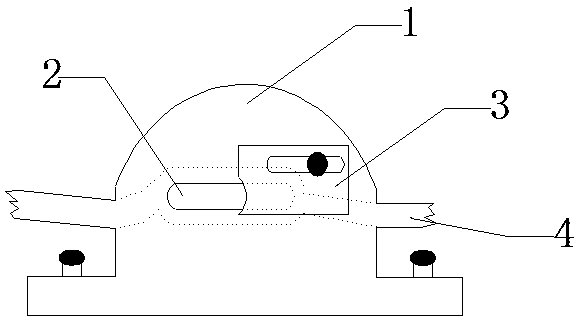
[0015] See figure 1 , The embodiment of the present invention includes:

[0016] A laser light barrier includes: a light barrier body 1, a laser through hole 2, an adjusting plate 3, and a cooling circulation system 4.

[0017] The light barrier body 1 is a metal flat plate with a thickness greater than 5 mm, the laser light hole 2 and the adjusting plate 3 are arranged in the middle of the light barrier body 1, and the bottom of the light barrier body 1 is provided with a base, The four corners of the base are provided with fi...


PUM


Abstract

The invention discloses a laser light barrier plate which comprises a light barrier plate body, a laser light through hole, an adjusting plate and a cooling circulation system. The middle of the light barrier plate body is provided with the laser light through hole and the adjusting plate, the light barrier plate body is fixed to an optical table through fixing screws installed on a base, the laser light through hole is a long light through hole, the adjusting plate is fixed to the light barrier plate body through a fixing screw, the adjusting plate is adjusted and fixed through a long adjusting hole and the fixing screw, light through holes of different sizes are formed between the laser light through hole the adjusting plate through the action of the adjusting hole and the fixing screw, and a water channel, an inlet in the water channel and an outlet in the water channel of the cooling circulation system are formed in the periphery of the laser light through hole and inside the light barrier plate body. In this way, the laser light barrier plate can adjust the laser light through hole according to the size of a laser light beam, and the unnecessary laser light beams can be blocked and absorbed through the adjustment of the light barrier plate for a plurality of laser light beams.

Description

technical field [0001] The invention relates to the field of light baffles, in particular to a laser light baffle. Background technique [0002] The general light baffle is a metal light baffle with a fixed light hole in the middle. When the size of the laser beam changes, it is not easy to make corresponding changes to this light baffle; Adjustment of the number of multiple laser beams passing through; and the general light baffle is not equipped with a cooling cycle system. For the laser light path that has been continuously working for a long time, the light baffle will cause sudden accidents in the light path due to overheating. Contents of the invention [0003] The technical problem mainly solved by the present invention is to provide a laser light baffle, which uses a thick metal plate as a light baffle to block the laser beam; the size of the light hole can be adjusted through the function of the adjustment plate; cool down. [0004] In order to solve the above t...

Claims


Application Information

Patent Timeline
IPC IPC(8): B23K26/06B23K26/70
CPCB23K26/703B23K26/066
Inventor 邹雄伟
Owner WUXI LIANCHUANG SHEET
Why Eureka
Try Eureka