Auxiliary clamping device with two positioning modes for turning process of steam turbine rotors

A steam turbine rotor and auxiliary clamping technology, which is used in positioning devices, turning equipment, metal processing equipment, etc., can solve the problems of small diameter adjustment, easy deformation, clamping of horizontal lathe chucks, etc. Easy-to-process effects

Inactive Publication Date: 2014-02-19
HARBIN TURBINE
View PDF9 Cites 7 Cited by
  • Summary
  • Abstract
  • Description
  • Claims
  • Application Information

AI Technical Summary

Problems solved by technology

[0003] The purpose of the present invention is to solve the problem of clamping turning of high and medium pressure rotors. Since there is no flange at the adjusting end of the high and medium pressure rotor, and the diameter of the adjusting end is small, it cannot be clamped by the chuck of a horizontal lathe. For other parts of the rotor, the parts clamped by the chuck of the horizontal lathe cannot be processed, and the outer circumferential surface of the flange of the electric end and the groove are thin and easily deformed, which affects the runout problem. A two-positioning method is provided. Auxiliary clamping device for steam turbine rotor turning

Method used


Image

  • Auxiliary clamping device with two positioning modes for turning process of steam turbine rotors
  • Auxiliary clamping device with two positioning modes for turning process of steam turbine rotors
  • Auxiliary clamping device with two positioning modes for turning process of steam turbine rotors

Examples


specific Embodiment approach 1

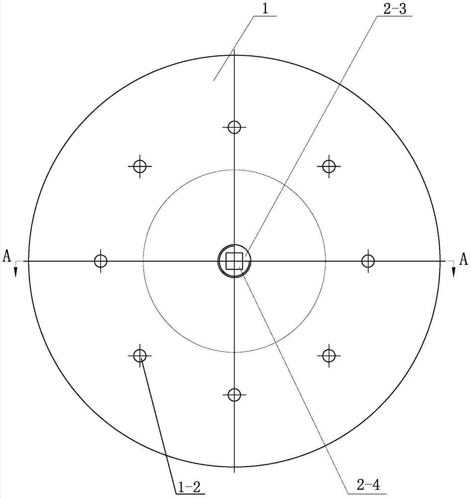
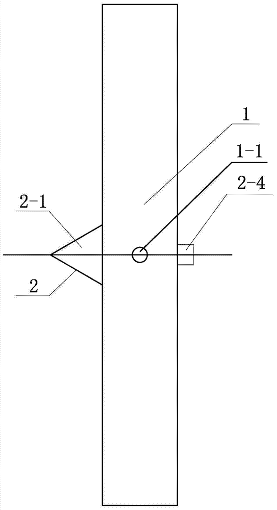
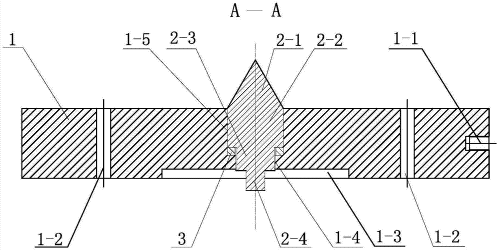
[0008] Specific implementation mode one: combine Figure 1-Figure 4 Explanation; the auxiliary clamping device for turning of steam turbine rotor with two positioning methods in this embodiment, the auxiliary clamping device for turning of steam turbine rotor with two positioning methods includes a disc 1, a positioning member 2 and a sleeve 3, The center of the end surface on one side of the disc 1 is coaxially provided with a concave stop 1-3 (counterbore) and a first threaded hole 1-4 from the outside to the inside, and a concave hole 1-4 is provided at the center of the end surface of the other side of the disc 1. The pin hole 1-5 connected with the seam 1-3 and the first threaded hole 1-4, the disc 1 is located on the same circumference and is uniformly processed with a plurality of through holes 1-2 penetrating the thickness of the disc 1, the disc 1 1. A second threaded hole 1-1 is processed radially on the outer peripheral surface. The positioning member 2 includes a c...


PUM


Abstract

The invention provides an auxiliary clamping device with two positioning modes for turning process of steam turbine rotors, and relates to an auxiliary clamping device for turning process of steam turbine rotors, aiming to solve problems that in the holding-type turning process of high and middle pressure rotors, the high and middle pressure rotors cannot be clamped well by chucks of horizontal lathes due to the fact that no flanges are arranged at adjusting ends of the high and middle pressure rotors and the adjusting ends have small diameters; if the electric ends are clamped for processing the other portions of the rotors, portions, clamped by the chucks, of the electric ends of the rotors, cannot be processed, and the electric ends are easy to deform to influence run-out due to thin outer circumference and groove walls of flanges at the electric ends. A stop recess, a first threaded hole and a pin hole are coaxially arranged at the center of one end face of a disc, a plurality of through holes running thorough the disc are uniformly machined in the disc on the same circumference, second threaded holes are radially processed on the outer circumference of the disc, a sleeve is arranged in the pin hole, a rectangular portion of a positioning part extends out of the stop recess from one side of the pin hole, and a second column of the positioning part is in threaded connection with the first threaded hole. The auxiliary clamping device is used for auxiliary clamp positioning in the turning process of the steam turbine rotors.

Description

technical field [0001] The invention relates to an auxiliary clamping device for steam turbine rotor turning. Background technique [0002] During the clamp-type turning of high and medium pressure rotors, because there is no flange (only the optical axis) at the adjustment end of the high and medium pressure rotor, and the diameter of the adjustment end is small, it cannot be clamped by the chuck of a horizontal lathe, so only the electric end can be clamped. Other parts of the rotor. However, the part clamped by the chuck of the horizontal lathe (the outer peripheral surface or end face of the electrical end flange, etc.) cannot be processed, and the outer peripheral surface and groove of the electrical end flange are thin and easily deformed, which affects the runout. Contents of the invention [0003] The purpose of the present invention is to solve the problem of clamping turning of high and medium pressure rotors. Since there is no flange at the adjusting end of the...

Claims


Application Information

Patent Timeline
Patent Type & Authority Applications(China)
IPC IPC(8): B23Q3/00
CPCB23Q3/00B23B23/02
Inventor 高岩朱建军罗小明柳薇翁振宇齐莹莹刘畅
Owner HARBIN TURBINE
Why Eureka
Try Eureka