Magnetic suction mechanism

A material suction mechanism and magnetic technology, applied in conveyors, conveyor objects, rotary conveyors, etc., can solve problems such as magnetic dispersion, poor directionality, and unloading steel bar failures.

Active Publication Date: 2014-02-19
NINGBO XINZHOU RESISTANCE WELDER
View PDF6 Cites 3 Cited by
  • Summary
  • Abstract
  • Description
  • Claims
  • Application Information

AI Technical Summary

Problems solved by technology

[0002] At present, there is a magnetic suction mechanism for conveying steel bars, which includes a frame, a motor and a roller. Several magnetic units are evenly distributed along the circumference of the roller on the cylindrical surface of the roller. The magnetic unit includes iron brackets, magnets, iron covers, iron The bracket is connected to the cylindrical surface of the drum, the magnets are installed on th

Method used


Image

  • Magnetic suction mechanism
  • Magnetic suction mechanism

Examples


Example Embodiment

[0012] The present invention will be further described below in conjunction with the drawings.

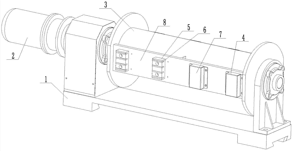
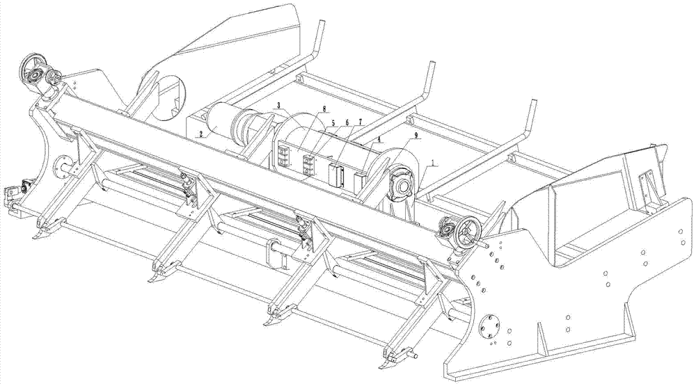
[0013] The magnetic suction mechanism of the present invention includes a frame 1, a motor 2 and a roller 3. It also includes multiple rows of magnetic units. The magnetic units in each row are evenly distributed along the circumference of the roller 3. Each magnetic unit 4 in each row of magnetic units Evenly distributed along the axis of the drum 3; the magnetic monomer 4 includes a bracket 5 made of antimagnetic material, a plurality of magnets 6, and a cover 7 made of antimagnetic material that can transmit magnetic force. The bracket 5 is connected to the cylindrical surface of the drum 3, A plurality of magnets 6 are uniformly arranged on the bracket 5 from top to bottom, and the cover 7 covers the bracket 5 to cover the plurality of magnets 6.

[0014] The cylindrical surface of the drum 3 is provided with supporting platforms 8 arranged axially. Each supporting platform 8 is use...


PUM


Abstract

The invention discloses a magnetic suction mechanism which has centralized magnetic force and good directionality; sucked rebars rarely cross-stack. The magnetic suction mechanism comprises a frame (1), a motor (2), a roller (3), and a plurality of rows of magnetic units, all evenly distributed on the periphery of the roller (3). The magnetic units (4) in each row are evenly distributed along the axial direction of the roller (3). Each magnetic unit (4) comprises a support (5) made of antimagnetic material, a plurality of magnets (6), and a cover (7) made of antimagnetic material admitting permeation of magnetism. Every support (5) is connected with the cylindrical surface of the roller (3). The magnets (6) are evenly arranged on the supports (5) from top to bottom. The covers (7) cover the supports (5) so as to cover the magnets (6).

Description

technical field [0001] The invention relates to the technical field of material conveying mechanisms, in particular to a magnetic material suction mechanism. Background technique [0002] At present, there is a magnetic suction mechanism for conveying steel bars, which includes a frame, a motor and a roller. Several magnetic units are evenly distributed along the circumference of the roller on the cylindrical surface of the roller. The magnetic unit includes iron brackets, magnets, iron covers, iron The bracket is connected to the cylindrical surface of the drum, the magnets are installed on the iron bracket, and the magnets are distributed longitudinally, and the corresponding horizontal direction is the axis direction of the drum. Since the iron bracket and iron cover are used, and the magnets are distributed longitudinally, the magnetic force is scattered and the directionality is poor. , the sucked-up reinforcement tends to cross and overlap each other, resulting in fail...

Claims


Application Information

Patent Timeline
IPC IPC(8): B65G29/00B65G47/92
Inventor 陈增光
Owner NINGBO XINZHOU RESISTANCE WELDER
Why Eureka
Try Eureka