Imaging module

A camera module and camera element technology, applied in image communication, TV, color TV, etc., can solve the problems of lightweight limit, easy deformation of through-hole shape, unstable external structure and bracket, etc. The effect of reducing usage

Inactive Publication Date: 2013-02-20
KYOCERA CORP
View PDF1 Cites 0 Cited by
  • Summary
  • Abstract
  • Description
  • Claims
  • Application Information

AI Technical Summary

Problems solved by technology

[0008] However, in the above-mentioned camera module, since the frame, which is a large part among the constituent parts, is made of metal, there is a problem that there is a limit in terms of weight reduction.
[0009] In addition, if only the bracket is made of resin, there is a problem that the shape of the through hole is easily deformed when the support pin for holding on the external structure such as the protective case is inserted into the through hole, so that the external structure Body and stent retention becomes unstable
In addition, there is also a problem that high-precision images cannot be obtained because one of the functions of the metal bracket is to shield electromagnetic interference from the subject side.

Method used


Image

  • Imaging module
  • Imaging module
  • Imaging module

Examples


Embodiment

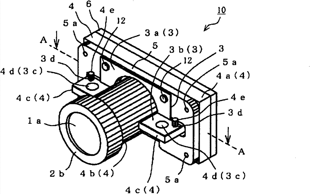
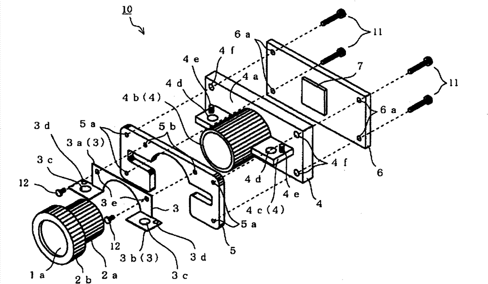
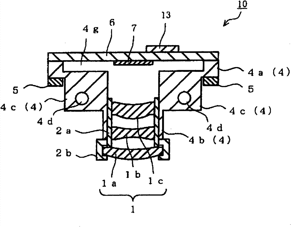
[0090] The camera module of the present invention was produced as follows.

[0091] First, a rectangular imaging substrate 6 is prepared. The imaging substrate 6 is provided with through holes 6a at four corners, has a longitudinal length of 20 mm, a lateral length of 40 mm, and a thickness of 1.6 mm. The imaging element 7 is mounted on the principal surface on the imaging body side, and the connector 13 and IC are mounted on the principal surface on the rear side.

[0092] Next, a resin material made of polyphthalamide is processed to produce a bracket 4 having a rectangular shape with through holes 4 f formed at four corners, a vertical length of 20 mm, a horizontal length of 40 mm, and a thickness of 4.0 mm. The substrate fixing portion 4a, the lens support cylindrical portion 4b with a diameter of 15mm formed with screw grooves on the inner wall, and the holding portion 4c provided with a through hole 4d with a diameter of 3.5mm.

[0093] Next, a stainless steel plate wit...


PUM


Abstract

An imaging module is provided that can be made lighter in weight, can be retained in an external structure with stability, and allows acquisition of high-resolution images. An imaging module (10) includes an imaging substrate (6) mounting an imaging device thereon, a resin holder (4) including a substrate securing portion (4a) to which the imaging substrate (6) is secured, a lens support barrel (4b) supporting a lens (1) at an inside thereof, and a holding portion (4c) which protrudes toward a subject from the substrate securing portion (4a) and includes a through hole (4d) configured to permit retention of the holder in an external structure, a metal securing member (5) disposed at a side of the substrate securing portion (4a) of the holder (4) facing a subject, and a metal holding plate (3) including a securing region which is secured to and electrically connected to the securing member (5), and a holding portion adjacent region (3b) which overlaps a part around the through hole (4d) of the holding portion (4c) and includes a through hole (3c) configured to communicate with the through hole (4d). The imaging module can be made lighter in weight, be retained in an external structure with stability, and allows acquisition of high-resolution images.

Description

technical field [0001] The present invention relates to an imaging module using an imaging element such as a semiconductor image sensor. Background technique [0002] For example, Patent Document 1 discloses, as a compact imaging module, an imaging module that uses a semiconductor image sensor such as a CCD image sensor or a CMOS image sensor as an imaging element that converts object light into an electrical signal, and has an imaging substrate and a metal The imaging substrate is mounted with an imaging element, and the metallic bracket is provided with a lens support cylinder that supports a lens that collects light from an object. [0003] In addition, in the imaging module described in Patent Document 1, the imaging board and the holder are fixed by screwing. Specifically, a through hole through which the screw passes is provided on the imaging substrate, and a screw screw hole is provided on the bracket, and the screw is inserted into the through hole of the imaging s...

Claims


Application Information

Patent Timeline
Patent Type & Authority Patents(China)
IPC IPC(8): H04N5/225G02B7/02G03B17/02H05K9/00
CPCG02B13/001G03B17/02H04N5/2252H04N5/2257G02B7/021H04N23/51H04N23/57
Inventor 冈田弘
Owner KYOCERA CORP
Why Eureka
Try Eureka