A laser-enhanced electrodeposition rapid prototyping device and method

A forming processing and laser strengthening technology, applied in the direction of electroforming, electrolysis process, etc., can solve the problems of adding templates for preparation and installation, metal parts with complex structures, and low precision of formed parts, so as to improve quality and performance, and highly selectivity , The effect of accelerating the charge transfer speed

Inactive Publication Date: 2016-11-23
TONGLING UNIV
View PDF4 Cites 0 Cited by
  • Summary
  • Abstract
  • Description
  • Claims
  • Application Information

AI Technical Summary

Problems solved by technology

Nanjing University of Aeronautics and Astronautics applied spray electrodeposition technology to the field of rapid prototyping technology, and proposed a selective electrodeposition process (CN00133282.1). During the forming process, the nozzle used as the anode sprays the high-speed flowing electrodeposition solution onto the surface of the cathode , the metal ions in the electrodeposition solution are continuously deposited under the action of an external electric field, and a layer of the part can be selectively deposited in a specific area by controlling the scanning motion of the nozzle, and a three-dimensional entity can be produced by layer-by-layer deposition superposition Prototype parts; spray electrodeposition adopts a special liquid phase mass transfer method, which increases the deposition rate by dozens or even hundreds of times, but due to the influence of jet localization, the precision of formed parts is not high
Zhejiang Sci-tech University organically combined electrochemical deposition technology, rapid prototyping technology and numerical control technology, and proposed the rapid prototyping technology of numerical control selective electrodeposition deposition, which can directly form and manufacture metal parts. Coupled with the limitation of the electrodeposition speed itself, the forming speed is slow
Patent CN200710025121.1 proposes a method of directly manufacturing metal parts by using laminated template electrodeposition technology. It deposits complex parts layer by layer in an electrodeposition system after layered die cutting, and finally obtains metal parts of the required shape. ; In order to effectively prevent the adsorption of impurities, avoid the generation of surface defects such as burrs and tumors, and obtain good electrodeposition uniformity, Nanjing University of Aeronautics and Astronautics recently proposed assisted grinding electrodeposition on the basis of stacked template electrodeposition technology. Deposition Forming Technology (Fan Hui, Huang Yinhui. Application of Auxiliary Grinding in Electroforming of Laminated Template[J]. Mechanical Science and Technology, 2013,32(5):722-725.) and Tribojet Electrodeposition Rapid Prototyping Technology (Tian Zongjun, Wang Guifeng, Huang Yinhui, et al. Jet electrodeposition rapid prototyping of nickel metal parts [J]. Journal of South China University of Technology, 2010, 38 (12): 41-44); but the electrodeposition technology based on stacked templates has increased The process of preparing templates and installing templates is eliminated, which makes the preparation process complicated
It can be seen that the above-mentioned various electrodeposition methods still have obvious deficiencies in the rapid preparation of metal parts with complex structures and high precision.

Method used


Image

  • A laser-enhanced electrodeposition rapid prototyping device and method
  • A laser-enhanced electrodeposition rapid prototyping device and method

Examples


Embodiment 1

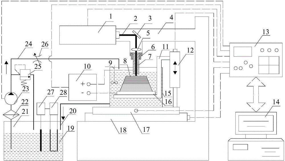
[0024] Such as figure 1 As shown, this embodiment includes a laser generating mechanism, an anode seat 6, an anode 7, a cathode, a power supply 10, a three-dimensional mobile platform, a working platform 11, a deposition tank 15, a constant temperature liquid storage mechanism and a controller 13; the anode 7 and the laser The generating mechanism is connected, the anode 7 is located in the anode seat 6, the deposition tank 15 is provided with an electrodeposition solution 19, the cathode is a deposition substrate 16, and the deposition substrate 16 is immersed in the electrodeposition solution 19 in the deposition tank 15, and the power supply 10 is respectively Connect the cathode and the anode 7; the three-dimensional mobile platform includes an X-axis mobile platform 17, a Y-axis mobile platform 18 and a Z-axis mobile platform 12, and one end of the working platform 11 is connected to the cathode, and the other end is connected to the Z-axis mobile platform 12, The X-axis mo...

Embodiment 2

[0037] This embodiment adopts laser-enhanced electrodeposition to rapidly form Cu metal parts on the graphite surface, and the specific steps are as follows:

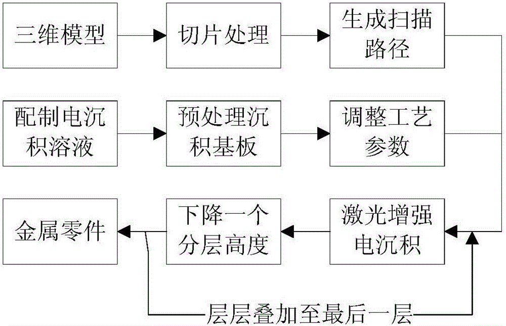
[0038] (1) First, the computer 14 performs three-dimensional modeling of the metal parts to be processed, and generates STL files, and then divides the three-dimensional solid model in STL format into many small thin layers through layering software, and generates according to the two-dimensional data of each thin layer section scan path;

[0039] (2) Preparation of electrodeposition solution 19: copper sulfate (CuSO 4 ·5H 2 O) 50g·L -1 , sulfuric acid (H 2 SO 4 ) 50g·L -1 , wetting agent (C 12 h 25 SO 4 Na) 0.1~0.2g·L -1 , brightener (saccharin) 1~3g·L -1 , the pH value is kept at 4±0.1, and the temperature of the electrodeposition solution 19 is kept at about 45°C; the graphite deposition substrate 16 is subjected to surface treatments such as polishing, degreasing, passivation, washing, and drying;

[0040...

Embodiment 3

[0043] This embodiment adopts laser-strengthened electrodeposition to rapidly form Ni-Mn alloy parts on the surface of 1Cr18Ni9Ti stainless steel, and the specific steps are as follows:

[0044] (1) First, the computer 14 performs three-dimensional modeling of the metal parts to be processed, and generates STL files, and then divides the three-dimensional solid model in STL format into many small thin layers through layering software, and generates according to the two-dimensional data of each thin layer section scan path;

[0045] (2) Preparation of electrodeposition solution 19: nickel sulfamate (Ni(NH 2 SO 3 ) 2 4H 2 O) 430~600g·L -1 , manganese sulfamate (Mn(NH 2 SO 3 ) 2 4H 2 O) 12~28g·L -1 , nickel chloride (NiCl 2 ·6H 2 O) 15~25g·L -1 , boric acid (H 3 BO 3 ) 30~35g·L -1 , wetting agent (C 12 h 25 SO 4 Na) 0.1~0.2g·L -1 , brightener (saccharin) 1~3g·L -1 , the pH value is kept at 4±0.1, and the temperature of the electrodeposition solution 19 is kept...


PUM


Abstract

The invention discloses a laser-enhanced electrodeposition rapid prototyping processing device and method, comprising a laser generating mechanism, an anode, an anode seat, a cathode, a power supply, a three-dimensional mobile platform, a working platform, a deposition tank, a constant temperature liquid storage mechanism and a controller. Laser irradiation causes the temperature of the electrodeposition solution / cathode interface area to rise, resulting in a decrease in the activation energy and overpotential of the electrode reaction, and an acceleration of the charge transfer rate; laser heating causes a large temperature gradient in the cathode surface area, causing electrodeposition in this area The slight agitation of the solution, on the one hand, reduces the thickness of the diffusion layer on the electrode surface; The speed of enhanced electrodeposition is greatly improved, thus achieving high-speed deposition. The deposition speed is fast, the forming precision is high, no shielding is required, and precision metal parts with complex shapes, dense structures, uniform structures and good mechanical properties can be directly and quickly manufactured.

Description

technical field [0001] The invention relates to a rapid prototyping processing technology, in particular to a laser-enhanced electrodeposition rapid prototyping processing device and method. Background technique [0002] Rapid prototyping technology (Rapid Prototyping, RP) starts from the CAD geometric model of the part, and through the software layered discrete and numerical control forming system, the material is piled up with a laser beam or other methods to form a solid part. Because it converts complex three-dimensional manufacturing into a series of two-dimensional manufacturing superpositions, it can generate almost arbitrarily complex parts without molds and tools, which greatly improves production efficiency and manufacturing flexibility. Since RP technology does not produce waste and cause environmental pollution in the process of manufacturing products, it is also a green manufacturing technology. [0003] With the development and application of new materials, es...

Claims


Application Information

Patent Timeline
Patent Type & Authority Patents(China)
IPC IPC(8): C25D1/00C25D5/00
Inventor 王东生田宗军周杏花朱坤锋季燕沈理达
Owner TONGLING UNIV
Why Eureka
Try Eureka