Large-cantilever steel box beam with highway and railway on same layer

A steel box girder and cantilever technology, applied in bridges, buildings, etc., can solve the problems of large longitudinal stress margin, poor wind resistance performance of blunt body section, and many rods, so as to achieve the reduction of transverse stress span and the occupation of interchanges. The effect of small area and saving engineering investment

Active Publication Date: 2014-02-19
CHINA RAILWAY SIYUAN SURVEY & DESIGN GRP
View PDF7 Cites 7 Cited by
  • Summary
  • Abstract
  • Description
  • Claims
  • Application Information

AI Technical Summary

Problems solved by technology

[0003] First of all, the layered layout of the road and railway has increased the elevation of the highway bridge deck, increased the length of the approach bridge, and correspondingly increased the construction cost;
[0004] Secondly, due to factors such as joint structure, many spliced ​​plates, and large slenderness ratio of weakened bolt holes, the material utilization rate of steel truss girders is not high, and the form of hybrid beams cannot be used, and the steel consumption is large;
[0005] Thirdly, the steel truss girder has a large overall cross-section height, many rods, a large wind resistance coefficient, and the blunt body cross-section has poor wind resistance.
[0006] Finally, there are many steel truss girder members. Although the transportation and hoisting are convenient, the splicing construction of the entire segment is difficult, while the splicing construction progress of a single member is slow and requires high construction accuracy.
[0007] The traditional road steel box girder has high torsional rigidity and good wind resistance, and the on-site hoisting accuracy requirements are slightly lower, and the mixed beam form can be used, but the bridge deck is widened after the railway is added in the middle of the section, so that the lateral force on the bridge deck increases sharply , while the longitudinal stress margin is large, the material utilization rate is not high, and the economy is poor

Method used


Image

  • Large-cantilever steel box beam with highway and railway on same layer

Examples


Embodiment Construction

[0023] The present invention will be further described in detail below in conjunction with the accompanying drawings and specific embodiments.

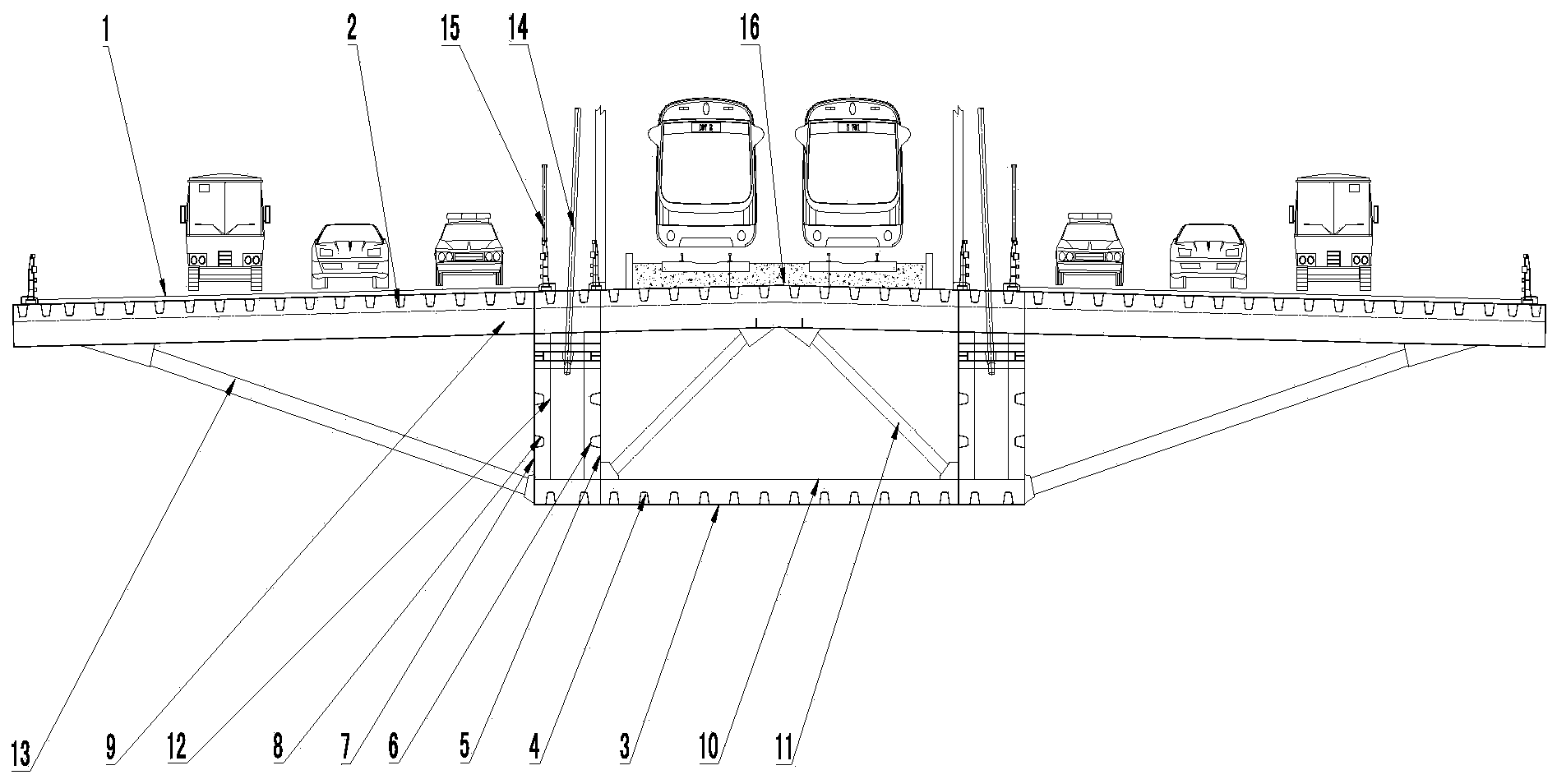
[0024] Such as figure 1 Shown is a large cantilever steel box girder on the same layer of public railway, which includes a box girder top plate 16 and a cantilever top plate 1. The cantilever top plate 1 is located on the longitudinal outer side of the box girder top plate 16. The cantilever top plate 1 is used to arrange roads, and the box girder top plate 16 is used for arranging the railway, the longitudinal sides of the lower end surface of the box girder top plate 16 are supported by load-bearing structures, the ends of the stay cables 14 are anchored in the load-bearing structure, and the bottom of the load-bearing structure is provided with a box girder bottom plate 3, and the box girder top plate 16 , the bearing structure and the bottom plate of the box girder 3 form a box structure. This design method, compared with the tra...


PUM


Abstract

The invention discloses a large-cantilever steel box beam with a highway and a railway on the same layer. The large-cantilever steel box beam comprises a box beam top board and cantilever top boards, wherein the cantilever top boards are located on the longitudinal outer sides of the box beam top board, the highway is arranged on the cantilever top boards, the railway is arranged on the box beam top board, the two longitudinal sides of the lower end face of the box beam top board are supported by load bearing structures, a box beam bottom board is arranged between the bottoms of the load bearing structures, and a box type structure is defined by the box beam top board, the load bearing structures and the box beam bottom board. According to the large-cantilever steel box beam with the highway and the railway on the same layer, the highway and the railway are arranged on the same layer, so that compared with a steel box beam with a traditional layered arrangement mode, the large-cantilever steel box beam has the advantages that the line elevation is small, the length of an approach bridge is small, the occupied range of the grade separation is small, project investment can be saved, the vision is wide, the landscape is good, and the novel large-span highway and railway combined construction bridge arrangement mode is achieved.

Description

technical field [0001] The invention relates to the technical field of bridge construction, in particular to a large cantilever steel box girder on the same floor for highways and railways. Background technique [0002] At present, domestic long-span bridges for road and railway use layered steel truss girders. Although the technology of steel truss girders is mature, there are still the following imperfections: [0003] First of all, the layered layout of the road and railway has increased the elevation of the highway bridge deck, increased the length of the approach bridge, and correspondingly increased the construction cost; [0004] Secondly, due to factors such as joint structure, many spliced ​​plates, and large slenderness ratio of weakened bolt holes, the material utilization rate of steel truss girders is not high, and the form of hybrid beams cannot be used, and the steel consumption is large; [0005] Thirdly, the steel truss girder has a large overall cross-sect...

Claims


Application Information

Patent Timeline
Patent Type & Authority Applications(China)
IPC IPC(8): E01D2/04
Inventor 罗世东刘振标曾敏任征马广张运波
Owner CHINA RAILWAY SIYUAN SURVEY & DESIGN GRP
Why Eureka
Try Eureka