A self-balancing prefabricated face, cast-in-place core-filled wall

A prefabricated surface, self-balancing technology, applied in the direction of walls, building components, buildings, etc., can solve the problems of low infill wall strength, increased cost of main structure, complicated construction process, etc. cost reduction effect

Active Publication Date: 2016-06-29
盐城市双新建设投资有限公司
View PDF5 Cites 0 Cited by
  • Summary
  • Abstract
  • Description
  • Claims
  • Application Information

AI Technical Summary

Problems solved by technology

The above-mentioned infill walls have the following problems: First, with the shortage of human resources in our country, labor costs have doubled, logistics costs have continued to increase, and the cost of infill walls has increased significantly; secondly, traditional floor slabs are generally 80-100 Reinforced concrete thin slabs have poor sound insulation and energy-saving performance, and can not be placed on any partition wall, which limits the flexibility of use; in addition, the low strength of the aerated concrete block filling wall is not conducive to safety and painting , Its high self-weight will increase the cost of the main structure, and its poor integrity is not conducive to the earthquake resistance of the structure, while the construction process of the hollow inner mold metal mesh cement inner partition wall is complicated and the construction period is longer

Method used


Image

  • A self-balancing prefabricated face, cast-in-place core-filled wall
  • A self-balancing prefabricated face, cast-in-place core-filled wall
  • A self-balancing prefabricated face, cast-in-place core-filled wall

Examples


Embodiment 1

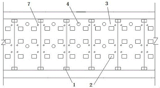
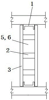
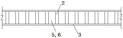
[0025] Such as Figure 1 to Figure 3 As shown, prefabricated components: prefabricated slab 3 (length 2850mm, width 1200mm, thickness 20mm) is attached with glass fiber mesh, the middle and top of the slab are provided with two pouring holes 4 with a diameter of 70mm, and the core material 6 is gypsum and cement (according to the volume ratio 3:1) it is delivered to the construction site after mass production in the factory assembly line, and the block connecting key 2 (length, width 100mm, thickness 80mm) is made of gypsum material and delivered to the construction site after mass production in the factory assembly line. The six connecting keys 2 and two prefabricated panels 3 are firmly assembled into a cavity mold, and the block positioning key 1 is mass-produced in the factory assembly line using recycled hard plastic (groove section, length 200mm, width 80mm, and 180mm). , thickness 80mm, wall thickness 10mm).

[0026] Core filling material 6: Set up locations in various...

Embodiment 2

[0032] At the junction of adjacent cavity molds (the two-sided prefabricated panels 3 are bonded to the connection key 2), use the tension key (which can be bound with iron wire) to pass through the tension joint hole 7 to connect and fix the adjacent prefabricated panels 3 on the same side, The rest are the same as Embodiment 1.

Embodiment 3

[0034] Drill two rows of six joint holes 7 in total on the prefabricated plate 3 of the cavity mold, pass through the tension joint holes 7 with a ring cable (that is, a strapping belt), and clamp the two sides with wooden pins to make the two sides of the prefabricated plate paired 3 Pull together to resist the tension during watering. The rest are the same as Embodiment 1.


PUM


Abstract

The invention provides a self-balancing prefabricated surface and cast-in-place core filling wall, which includes positioning keys (1) arranged at intervals along the direction of the filling wall, and the two sides of the positioning key (1) are prefabricated panels connected by connecting keys (2) (3), there is at least one pouring hole (4) in the middle and upper end of the prefabricated slab (3), and a cavity (5) is formed between the paired prefabricated slabs (3), and the cavity (5) is filled with core material (6 ). Because the wall surface of the present invention adopts the prefabricated panels prefabricated and produced in batches by the factory, the requirement for the core filling material is reduced, the materials are widely used, and the cost is reduced. Wall prefabrication eliminates the need for construction templates, and the two prefabricated walls are connected internally to form a cavity mold, thereby eliminating the need for external construction and fixing measures, which greatly simplifies the construction process. The adoption of quick-setting core material is conducive to the timely disassembly and turnover of construction tools. The mechanization of the whole process from batching to pouring can greatly save labor, improve efficiency and reduce costs.

Description

technical field [0001] The invention relates to a building filling wall, in particular to a self-balancing prefabricated surface and cast-in-place core filling wall. Background technique [0002] Building infill walls and floor slabs are the maintenance structures of buildings. They are large in quantity and wide in area. Their performances such as sound insulation, heat insulation, strength, fire prevention, moisture resistance, and water resistance directly affect the usability and safety performance of buildings. With the progress of the times and the requirements of environmental protection, the era of Qin bricks and Han tiles has come to an end, and new wall materials have been introduced continuously. broadly used. The above infill walls have the following problems: First, with the shortage of human resources in our country, labor costs have doubled, logistics costs have continued to increase, and the cost of infill walls has increased significantly; secondly, traditi...

Claims


Application Information

Patent Timeline
Patent Type & Authority Patents(China)
IPC IPC(8): E04B2/86
Inventor 谢孟谢琦
Owner 盐城市双新建设投资有限公司
Why Eureka
Try Eureka