Air valve bridge assembly, in-cylinder brake system and engine

A valve bridge and assembly technology, applied in engine components, machines/engines, mechanical equipment, etc., can solve the problems of increased engine weight, affected braking power, insufficient brake exhaust valve 8 lift, etc. Dynamic load, improved reliability, compact structure

Active Publication Date: 2019-02-19
WEICHAI POWER CO LTD
View PDF8 Cites 6 Cited by
  • Summary
  • Abstract
  • Description
  • Claims
  • Application Information

AI Technical Summary

Problems solved by technology

If the seal is not tight, it will lead to insufficient lift of the brake exhaust valve 8, which will affect the braking power; and due to the increase in the number of parts, the weight of the engine will increase accordingly

Method used


Image

  • Air valve bridge assembly, in-cylinder brake system and engine
  • Air valve bridge assembly, in-cylinder brake system and engine
  • Air valve bridge assembly, in-cylinder brake system and engine

Examples


Embodiment Construction

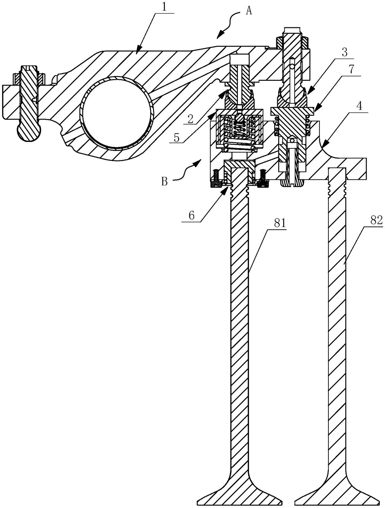
[0055] The core of the present invention is to provide a valve bridge assembly, which greatly reduces the braking load and improves the reliability of the gas distribution mechanism under braking conditions during the compression release braking process.

[0056] The present invention also provides an in-cylinder braking system comprising the valve bridge assembly and an engine comprising the in-cylinder braking system, which greatly reduces the braking load and improves the braking performance during the compression release braking process. The reliability of the valve train under certain conditions.

[0057] In order to make the purpose, technical solutions and advantages of the embodiments of the present invention clearer, the technical solutions in the embodiments of the present invention will be clearly and completely described below in conjunction with the drawings in the embodiments of the present invention. Obviously, the described embodiments It is a part of embodimen...


PUM


Abstract

The invention discloses an engine, an in-cylinder brake system and an air valve bridge assembly. The air valve bridge assembly comprises a main piston mounting hole and a brake piston mounting hole, wherein the main piston mounting hole is formed in the inner side end of an air valve bridge body; the brake piston mounting hole is formed below the main piston mounting hole and communicates with themain piston mounting hole; an oil unloading assembly mounting hole is formed in the outer side end; an air valve bridge oil duct communicating the piston mounting hole with the oil unloading assemblymounting hole is formed in the air valve bridge body; a main piston assembly is mounted in the main piston mounting hole; a brake piston assembly is mounted in the brake piston mounting hole; an oilunloading assembly is mounted in the oil unloading assembly mounting hole; the in-cylinder brake system comprises an exhausting rocker arm assembly and an air valve bridge assembly; and a ball pin assembly keeping contact with the main piston assembly and an adjusting screw assembly keeping contact with the oil unloading assembly are arranged on the air valve side of the rocker arm body of the exhausting rocker arm assembly. The load transmitted to a push rod side by the in-cylinder brake system is greatly reduced, so that separation of the rocker arm and the air valve bridge is prevented, thefailure that a rocker arm elephant foot overturns and is knocked to be damaged is avoided, and the reliability is greatly improved.

Description

technical field [0001] The invention relates to the technical field of engines, in particular to a valve bridge assembly, an in-cylinder braking system including the valve bridge assembly, and an engine including the in-cylinder braking system. Background technique [0002] When the engine is doing positive work, the engine completes four working cycles of intake, compression, work and exhaust during the 360° rotation of the camshaft. At the end of the compression stroke, fuel is injected into the cylinder to burn, and it does work on the outside during the subsequent expansion stroke. [0003] When the engine brakes, the engine needs to open the exhaust valve with a small lift (1~2mm) under the drive of the engine brake device when the compression stroke is close to the top dead center, and release the compressed high-pressure gas in the cylinder quickly. , the pressure in the cylinder decreases rapidly to reduce the energy of the power stroke, so in the next power stroke,...

Claims


Application Information

Patent Timeline
Patent Type & Authority Applications(China)
IPC IPC(8): F01L1/26F01L13/06
CPCF01L1/26F01L13/065
Inventor 王刚许成李栋马高强辛文华
Owner WEICHAI POWER CO LTD
Why Eureka
Try Eureka