High energy screw press

A screw press, high-energy technology, applied to presses, stamping machines, forging presses, etc., can solve problems such as poor guidance, noise of air pumps, and difficulty in tight contact, so as to improve guidance and sealing performance and reduce installation accuracy requirements , Good effect of processing technology performance

Inactive Publication Date: 2005-05-04
夏天赳 +1
View PDF1 Cites 4 Cited by
  • Summary
  • Abstract
  • Description
  • Claims
  • Application Information

AI Technical Summary

Problems solved by technology

[0003] 1. The seal between the sealing ring 7 and the piston 3 is an end face seal, but the size of the two is large and the orientation is poor, so it is very difficult to ensure that all of them are in close contact
The gap between the inner diameter of the sealing ring and the support frame is difficult to control: if the gap is too large, a large amount of high-pressure oil in the auxiliary oil chamber will leak out, which will not only cause a large amount of energy loss, but also the pressure of the auxiliary oil chamber is too low to ensure the pressure of the end face seal. If the gap is too small, under the action of high-pressure oil, the sealing ring will cling to the support frame to generate a lot of friction. During the striking process, the piston will retreat upwards, and the sealing ring will not be able to keep up with it in time, resulting in sealing failure.
[0004] 2. The structure of the pressure relief system is too complicated
Each action takes a certain amount of time, and the pressure relief process is slow
[0005] 3. The pressure sensor needs to be equipped with a compressed air pump, an air storage tank, and a pressure regulating valve system, and the air pump is noisy
After the sensor is turned on, because the compressed air is not discharged immediately, it is prone to combo
[0006] 4. The slider balance cylinder consumes a lot of energy in the downstroke, and the flywheel decelerates significantly

Method used


Image

  • High energy screw press
  • High energy screw press

Examples


Embodiment Construction

[0017] Embodiments of the present invention are as follows:

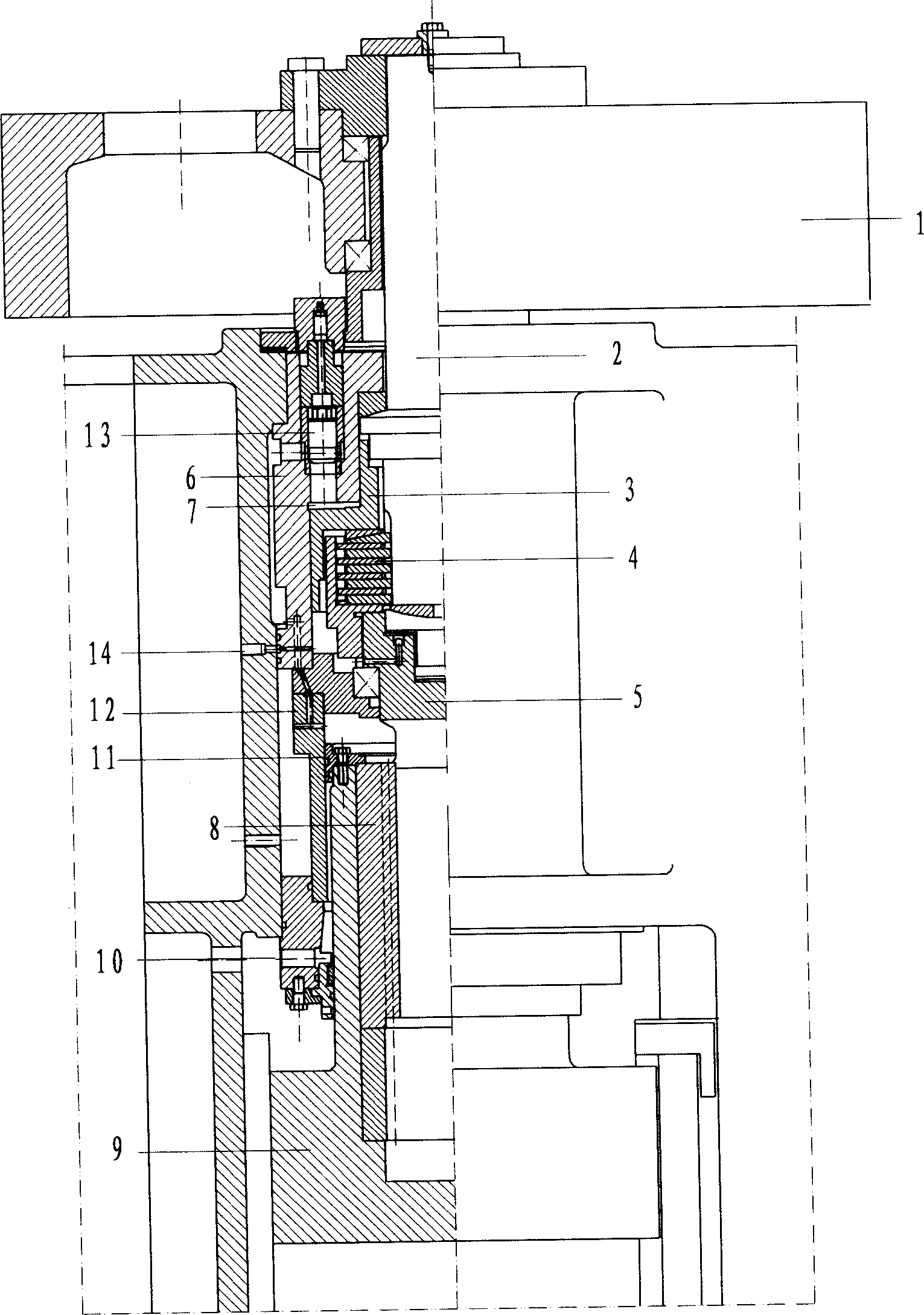
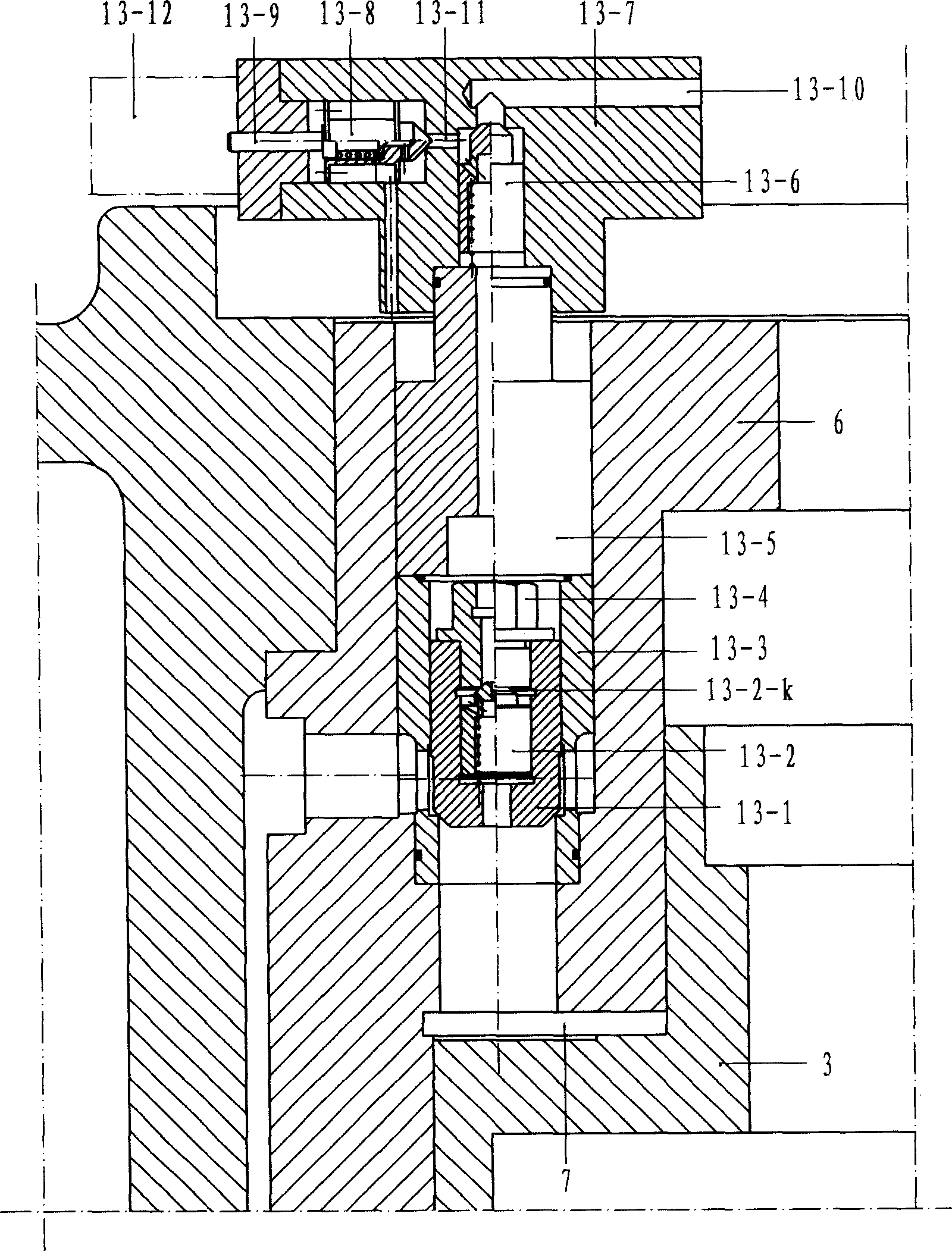
[0018] When the present invention is in a static state, the slider stays at the uppermost position by the hydraulic oil sealed in the annular return cylinder. The compression piston 3 is under the action of the 0.2MPa low-pressure oil at the bottom of the compression cylinder, so that the clutch driving plate and the driven plate are in a loose state. When starting, the electromagnet 13-12 is energized, and the electromagnetic suction presses the pilot spool 13-8 tightly on the aperture 13-11 through the control valve 13-9. At the same time, the return cylinder 12 discharges oil to the oil tank of the hydraulic oil supply system through the oil inlet and outlet ports 10, the slide block 9 falls freely under the action of gravity, and the screw rod 5 is driven by the nut 8 to rotate forward and accelerate. After a certain time delay, the hydraulic system enters the oil through the oil inlet 13-10 of the valve seat 1...


PUM


Abstract

The present invention is a quick pressure-relieving high-energy screw press for implementing die forging and finish forging process instead of friction press and hot die forging press. Said invented screw press is formed from machine body, motor, pulley, freewheel, screw rod, nut, slide block return system, clutch and its compression system, pressure-relieving system, hydraulic system and circuit system. The pressure-relieving system adopts electromagnetic hydraulic sensor, and the oil pressure in the compression cylinder can be increased with the increment of processing force, and when the oil pressure is reached to the electromagnetic current set value, the electromagnetic hydraulic sensor can act, and can utilize pilot valve and main valve to implement quick pressure relief, the lower cavity of piston is filled with low pressure oil with 0.2 MPa, and between the piston and friction disk and between driving shaft and screw rod the spherical pads are mounted.

Description

1. Technical field [0001] The invention belongs to heavy material processing equipment, and is a quick-release high-energy screw press used in die forging and precision forging processes instead of the currently widely used friction presses and hot die forging presses. 2. Background of the invention [0002] At present, the high-energy screw press used in the material processing industry is a product developed in Germany in the 1970s. This type of press is composed of a bed, a motor, a pulley, a flywheel, a clutch, a screw, a nut, a slider, a return cylinder, and a hydraulic system. It is disengaged from the screw to realize the termination strike and the return stroke of the slider. It eliminates the shortcomings of frequent starting of electric screw presses, short life of AC contactors caused by forward and reverse rotation, and large impact on grid power during operation. It does not need to be equipped with a huge hydraulic station like hydraulic screw presses. These ...

Claims


Application Information

Patent Timeline
Patent Type & Authority Applications(China)
IPC IPC(8): B21J9/00B30B1/23
Inventor 夏天赳夏思淝
Owner 夏天赳
Why Eureka
Try Eureka