Abrasion resistance finned tube and heat exchanger

A wear-resistant, finned tube technology, applied in tubular elements, heat exchange equipment, lighting and heating equipment, etc., can solve the problems of rigidity, low elastic compensation capacity, high heat transfer efficiency of finned tubes, and insufficient finned surface area, etc. , to achieve the effect of improving the flow field, large heat transfer area and high heat transfer efficiency

Inactive Publication Date: 2015-11-04
SOUTHEAST UNIV +1
View PDF9 Cites 5 Cited by
  • Summary
  • Abstract
  • Description
  • Claims
  • Application Information

AI Technical Summary

Problems solved by technology

However, the rigidity and elastic compensation ability of the diaphragm tube row is lower than that of the light tube, and the finned surface area is far less than that of the traditional spiral fin tube, and the heat transfer enhancement effect is poor.
[0007] In short, most of the existing finned tube designs are at the expense of sacrificing the heat transfer area and reducing the heat transfer efficiency, which seriously affects the advantages of high heat transfer efficiency of traditional finned tubes

Method used


Image

  • Abrasion resistance finned tube and heat exchanger
  • Abrasion resistance finned tube and heat exchanger
  • Abrasion resistance finned tube and heat exchanger

Examples


Embodiment 1

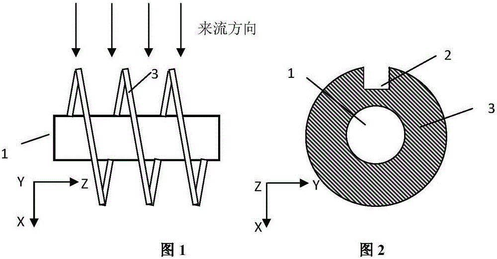
[0043] figure 1 , figure 2 shown. The fin tube of the present invention comprises a base tube 1 and fins 3, wherein 1 is a base tube, and the fin 3 is a spiral fin. A rectangular drainage groove 2 is provided on the facing surface of the spiral fin, which is similar to a C shape. In this embodiment, the height of the drainage groove is 2 / 3 of the height of the fin, and the width of the drainage groove is 1 of the diameter of the base pipe. / 5, welding the slotted spiral fins to the base tube 1, or slotting the fins 3 of the existing spiral fin tubes.

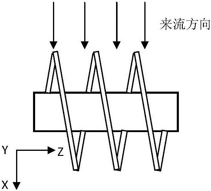
[0044] Apply Fluent commercial software to the traditional spiral finned tube of a certain structural size ( Figure 5 , Figure 6 ), H-shaped finned tube ( Figure 7 , Figure 8 ) and the slotted spiral fin tube of the present invention ( figure 1 , figure 2 ) for numerical simulation of the external flue gas flow:

[0045] The flue gas velocity outside the finned tube is 6m / s, and flows along the positive directio...

Embodiment 2

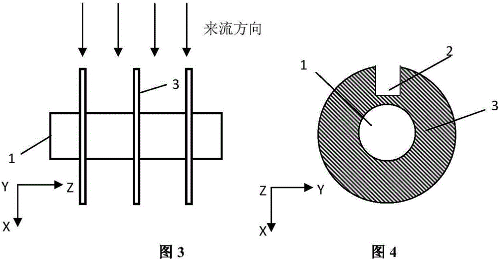
[0054] image 3 , Figure 4 shown. The C-shaped circular finned tube of the present invention includes a base tube 1 and fins 3, wherein 1 is a base tube, and the fins 3 are circular parallel fins. A rectangular drainage groove 2 is provided on the facing surface of the spiral fin. In this embodiment, the height of the drainage groove is 4 / 5 of the height of the fin, and the width of the drainage groove is 1 / 5 of the diameter of the base pipe. The simulation obtains the C-type circular fin tube of the present invention and the traditional circular fin tube ( Figure 9 , Figure 10 ) The wear rate diagram of the upstream surface of the base pipe is shown in Figure 15 .

[0055] Depend on Figure 15 It can be seen that the wear rate of the base tube of the C-type circular finned tube of the present invention is lower than that of the traditional circular finned tube, and the wear area is also smaller than that of the traditional circular finned tube. The wear rate of the...


PUM


Abstract

The invention discloses an abrasion resistance finned tube and a heat exchanger. The abrasion resistance finned tube comprises a base tube and fins arranged on the outer surface of the base tube. The abrasion resistance finned tube is characterized in that a drainage groove with an opening at the upper end is formed in the incident flow surfaces of the fins, and the height of the drainage groove is 1/2 to 4/5 of the height of the fins; and the width of the drainage groove is 1/6-1/4 of the diameter of the base tube; and the fins are parallel fins or spiral fins arranged at internals. Compared with the prior art, according to the abrasion resistance finned tube, the groove is formed in the incident flow surfaces of the fins on spiral or circular finned tubes, the influence on the extension surface area of the finned tubes is not large, and the advantage of large heat exchange areas of the finned tubes is retained. Through the adjustment of the height and the width of the drainage groove, the abrasion condition of traditional spiral finned tubes or circular finned tubes is effectively improved, and the abrasion resistance property is superior to that of H type finned tubes. Meanwhile, since the fins of the abrasion resistance finned tube are in a circular arc shape, the advantage of the abrasion resistance property of the fins is more obvious than the advantage of the H type finned tubes

Description

technical field [0001] The invention is applied in the field of boiler flue heat exchangers, and in particular relates to a finned tube which can effectively improve the wear resistance of the heat exchange tube and a heat exchanger with the finned tube. Background technique [0002] Finned tubes are one of the important heat exchange elements for recovering waste heat and enhancing heat transfer in industry. They are widely used because of their compact structure, increasing the total effective area participating in convective heat transfer, and reducing the thermal resistance of heat transfer outside the tube. . Commonly used finned tubes in the industry include circular finned tubes, H-shaped finned tubes, and spiral finned tubes. When the dust-laden flue gas flows through the heat exchanger to scour the heating surface, the flue gas particles in the air flow collide with the tube wall, which will cause wear to the fin tube over time, and the fin tube wear will affect th...

Claims


Application Information

Patent Timeline
Patent Type & Authority Applications(China)
IPC IPC(8): F28F1/24F28F1/36
Inventor 赵伶玲钟磊周强泰
Owner SOUTHEAST UNIV
Why Eureka
Try Eureka