Device for recycling waste heat of flue gas in power station boiler

A technology for flue gas waste heat and power station boilers, which can be used in cleaning heat transfer devices, preheating, liquid degassing, etc., and can solve problems such as heat waste

Inactive Publication Date: 2010-09-08
史振玺
View PDF6 Cites 8 Cited by
  • Summary
  • Abstract
  • Description
  • Claims
  • Application Information

AI Technical Summary

Problems solved by technology

Generally, the exhaust gas temperature of power plant boilers is between 110°C and 130°C, and the exhaust gas loss of the entire

Method used


Image

  • Device for recycling waste heat of flue gas in power station boiler
  • Device for recycling waste heat of flue gas in power station boiler
  • Device for recycling waste heat of flue gas in power station boiler

Examples


Embodiment Construction

[0009] The specific structure of the present invention is illustrated below in conjunction with the embodiment given with accompanying drawing.

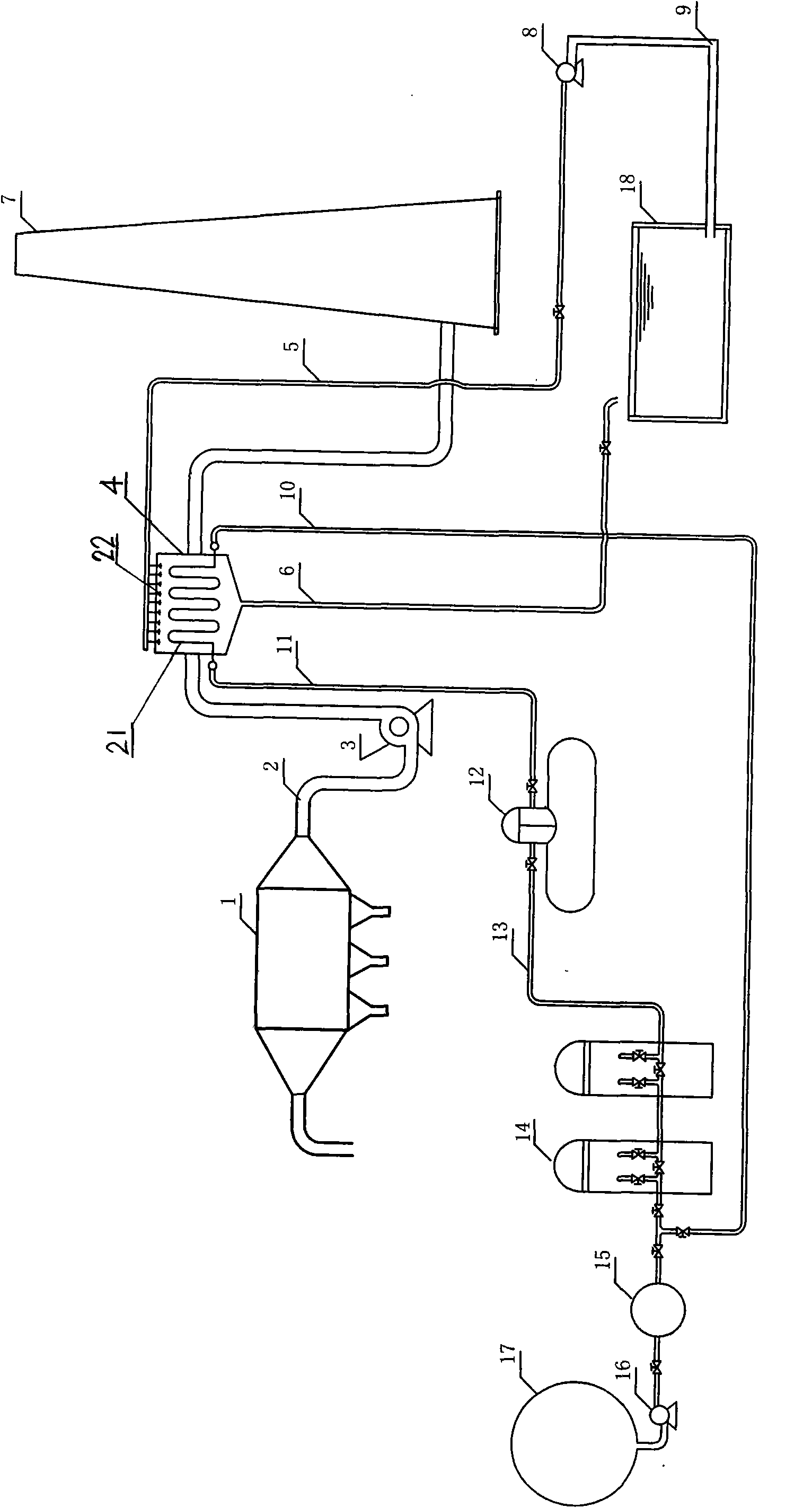
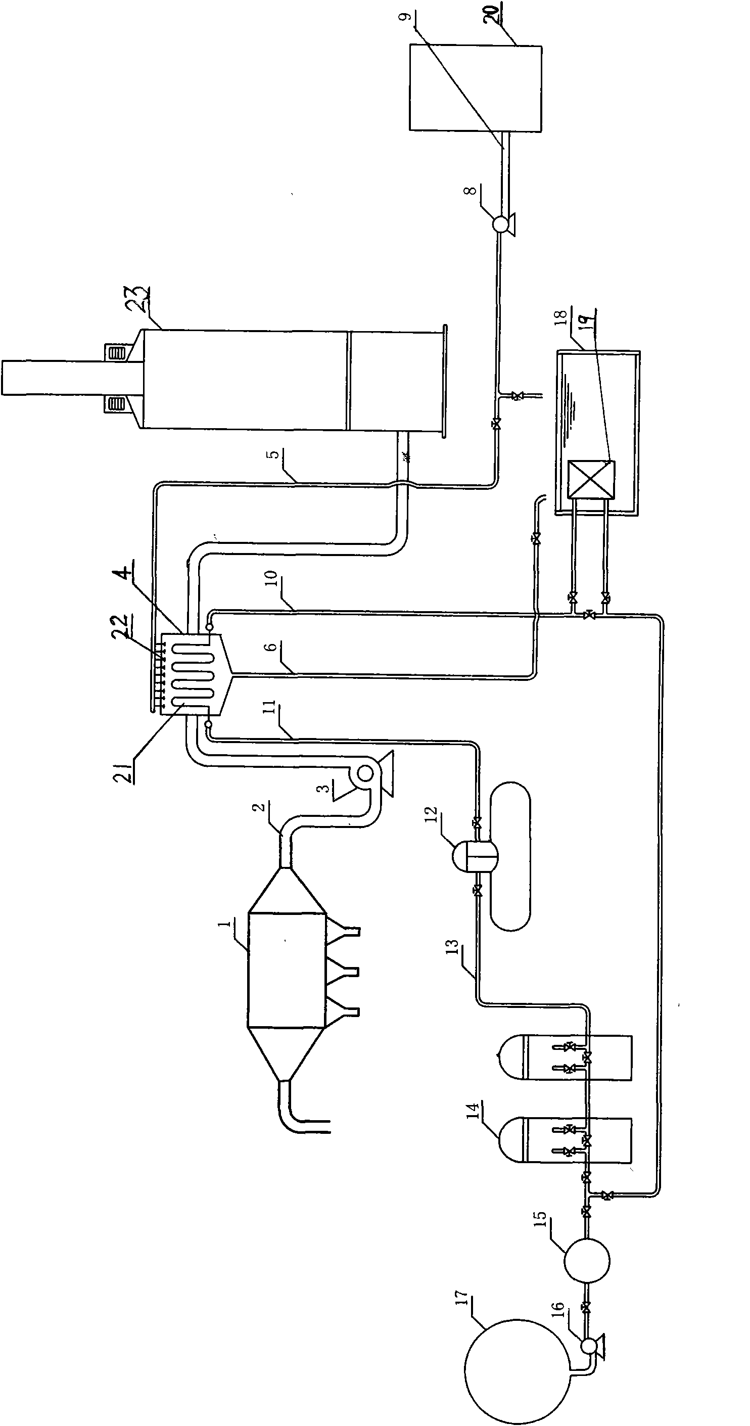
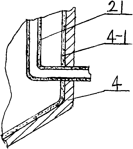
[0010] As shown in the figure, the utility boiler flue gas waste heat utilization device of the present invention has a heat exchanger inlet pipe 10, one end of which is connected to the pipeline between the shaft seal heater 15 and the low-pressure heater 14, and the other end is connected to the heat exchanger 4 The inner serpentine pipe 21 is connected, the other end of the serpentine pipe is connected with the deaerator 12 through the return pipe 11 of the heat exchanger, the deaerator is connected with the low-pressure heater 14 through the pipeline 13, and the bottom of the heat exchanger 4 is connected with cleaning water The return pipe 6 and the nozzle 22 on the upper part of the heat exchanger 4 are connected to one end of the cleaning water pipe 5, and the other end of the cleaning water pipe is connected to the sump 18 or ...


PUM


Abstract

The invention provides a device for recycling waste heat of flue gas in a power station boiler, which is characterized in that one end of a water inlet pipe of a heat exchanger is communicated on a pipeline between a gland heater and a low pressure heater; the other end of the water inlet pipe is communicated with a coil in the heat exchanger; the other end of the coil is connected with a deaerator through a water return pipe of the heat exchanger; the deaerator is connected with the low pressure heater through the pipeline; a clean water return pipe is arranged at the bottom of the heat exchanger; a nozzle is arranged at the upper part of the heat exchanger and is communicated with one end of a clean water pipe; the other end of the clean water pipe is connected with a water collecting tank or a desulfurizer storing pot; one end of a flue pipe is connected with an electrostatic dust collector through a draught fan; and the other end of the flue pipe is communicated with a chimney or a desulfurizing tower through the heat exchanger. The device for recycling waste heat can recycle most of heat in the flue gas discharged from the boiler and can convert the recycled heat into the heat of the condensation water of a steam turbine, thereby reducing the steam consumption of the low pressure heater in a heat regenerative system of the steam turbine and saving a large amount of energy sources. A cleaning device is arranged in the heat exchanger, thereby ensuring the cleanness and the heat exchange efficiency of a heat exchange surface.

Description

technical field [0001] The invention provides a boiler flue gas waste heat utilization device. Background technique [0002] At present, the exhaust smoke of power plant boilers is sucked by the boiler induced fan, enters the electrostatic precipitator for dust removal treatment, removes most of the coal ash in the flue gas, and then is transported to the chimney exhaust or desulfurization device for desulfurization treatment through the boiler induced fan. This process only removes dust and desulfurizes the flue gas, and does not utilize the heat of the flue gas. Generally, the exhaust gas temperature of power plant boilers is between 110°C and 130°C. The exhaust gas loss of the entire boiler accounts for about 5% to 10% of the boiler efficiency. A large amount of heat in the flue gas is wasted without being used. Contents of the invention [0003] The problem to be solved by the present invention is to provide a utility boiler flue gas waste heat utilization device to f...

Claims


Application Information

Patent Timeline
IPC IPC(8): F22D1/50F22D11/06F28G9/00
Inventor 史振玺邢晖
Owner 史振玺
Why Eureka
Try Eureka