Driving device and its manufacturing method

A driving device and manufacturing method technology, which is applied in the direction of machines/engines, mechanical power generating mechanisms, mechanical equipment, etc., can solve problems such as disconnection, cumbersome operations, and concentration, and achieve the effect of reliable connection

Inactive Publication Date: 2016-05-11
SMK CO LTD
View PDF3 Cites 0 Cited by
  • Summary
  • Abstract
  • Description
  • Claims
  • Application Information

AI Technical Summary

Problems solved by technology

[0007] However, in the above-mentioned conventional technology, the work of fixing each of the very thin shape memory alloy wires to the base member by screwing or the like is very cumbersome, resulting in a problem of poor work efficiency.
[0008] In addition, since the shape memory alloy wire is repeatedly deformed, the stress during the deformation tends to concentrate on the part fixed by a screw or the like, and there is a possibility of breaking the wire.

Method used


Image

  • Driving device and its manufacturing method
  • Driving device and its manufacturing method
  • Driving device and its manufacturing method

Examples


Embodiment Construction

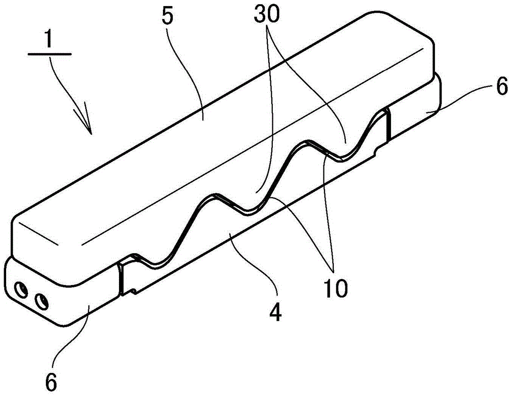
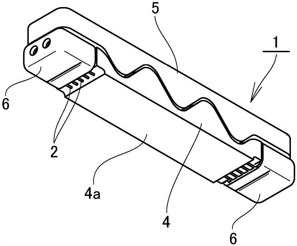
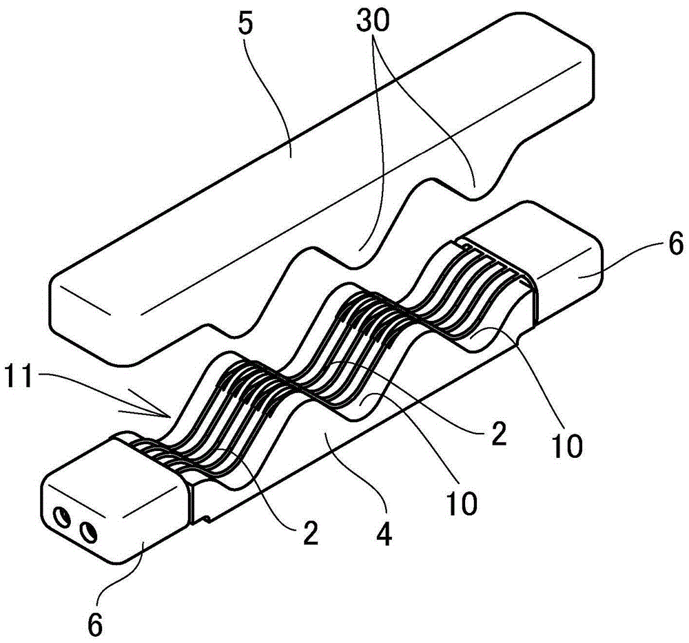
[0046] Next, based on Figure 1~Figure 10 The illustrated embodiment explains the implementation of the driving device of the present invention. Among them, the symbol 1 in the figure is a driving device, and the symbol A is a printed wiring board on which the driving device 1 is mounted.

[0047] The driving device 1 includes: linear shape memory alloy members 2, 2...; an insulating base member 4 having a fixing portion 3 for fixing the ends of the shape memory alloy members 2, 2...; and shape memory alloy members 2, 2 The movable member 5 moves relative to the base member 4 in conjunction with the shrinkage caused by the energization and heat; and the urging force is applied to the movable member 5 in the direction that the shape memory alloy members 2, 2... become the non-energized shape unit.

[0048] In addition, the drive device 1 is provided with terminal fittings 6 and 6 fitted with the fixing portion 3, and the bottom surface of the terminal fitting 6 is connected to the...


PUM


Abstract

The invention provides a driving device that enables easy installation and excellent manufacture efficiency of shape memory alloy parts, and a method of manufacturing the same. The driving device comprises shape memory alloy parts (2, 2...), a base body part (4) having fixing portions (3, 3), a movable part (5) that moves relative to the base body part in a way that the shape memory alloy parts contract because power is on , a force applying unit for applying force to the movable part in a direction when the shape memory alloy parts are in a shape under a power-off state, and a terminal fitting (6) that has press plates (20, 21) covering all sides of the fixing portions and is embedded with the fixing portions. An end basic side (2a) of each shape memory alloy part is configured along the surface of each fixing portion, and an end front side (2b) of each shape memory alloy part is configured along the back side of each fixing portion from an end surface portion (14) to a back side of each fixing portion in a returning manner. The end basic side and the end front side are clamped between the fixing portions and the press plates.

Description

Technical field [0001] The present invention relates to a driving device using a shape memory alloy and a manufacturing method thereof. Background technique [0002] In the past, the following drive devices have been widely used in camera lens drive actuators, etc. The drive device utilizes the characteristics of shape memory alloys, that is, even if it is deformed by force, it shrinks if heated to a certain temperature (operating temperature) by energization. The characteristics of the drive (for example, refer to Patent Document 1). [0003] The driving device includes an insulating base member and a movable member opposed to the base member, and a plurality of shape memory alloy wires that shrink due to heat generated during energization are arranged in parallel between their facing surfaces. When energized, the movable member is urged by the urging unit toward the base member, and the shape memory alloy wire is pressed against the movable member to be bent. When energized, the...

Claims


Application Information

Patent Timeline
Patent Type & Authority Patents(China)
IPC IPC(8): F03G7/06
Inventor 松田健小室雅司
Owner SMK CO LTD
Why Eureka
Try Eureka