A ultrasonic positioning method and a ultrasonic positioning system

A positioning method and technology of a positioning system, which are applied in directions such as beacon systems using ultrasonic/sonic/infrasonic waves, can solve problems such as low accuracy and inability to determine whether a mobile device has entered

Active Publication Date: 2014-02-19
广州光点信息科技股份有限公司
View PDF4 Cites 6 Cited by
  • Summary
  • Abstract
  • Description
  • Claims
  • Application Information

AI Technical Summary

Problems solved by technology

[0003] However, in terms of mobile device positioning, the current mobile device positioning systems use GPS satellites to achieve positioning. Although the GPS satellite positioning system can be used to determine whether a mobile device is in a certain area on the ground, its accuracy is low. Generally, it can only be determined that the mobile device has entered a larger area, and it is impossible to determine whether the mobile device has entered a smaller area such as a store or school.

Method used


Image

  • A ultrasonic positioning method and a ultrasonic positioning system
  • A ultrasonic positioning method and a ultrasonic positioning system
  • A ultrasonic positioning method and a ultrasonic positioning system

Examples


no. 1 example

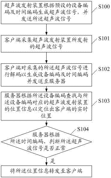
[0024] figure 1 It is a flow chart of the first embodiment of an ultrasonic positioning method of the present invention, including:

[0025] S100. The ultrasonic emitting device generates an ultrasonic signal according to a preset device code and time code, and sends the ultrasonic signal.

[0026] It should be noted that a unique binary device code is preset in the ultrasonic transmitter device. At the same time, the ultrasonic transmitter device can collect the current time in real time and convert it into a time code. At the same time, the device code and time code are used as source information, and The source information is encoded to generate a corresponding ultrasonic signal.

[0027] More preferably, the ultrasonic emission device is programmed with computer preset equipment code and time code.

[0028] It should be noted that the equipment code in the ultrasonic emitting device is unique, while the time code changes in real time. The time code adopts a self-increme...

no. 2 example

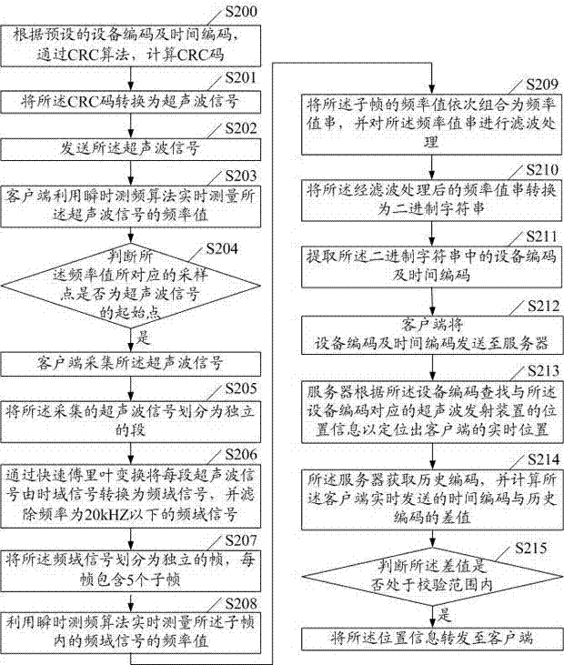
[0038] figure 2 It is a flow chart of the second embodiment of an ultrasonic positioning method of the present invention, including:

[0039] S200. Calculate a CRC code through a CRC algorithm according to the preset device code and time code.

[0040] It should be noted that the ultrasonic emitting device is preset with a unique binary equipment code, and at the same time, the ultrasonic emitting device can collect the current time in real time and convert it into a binary time code. And the device code and time code are used as source information. Use the CRC algorithm to calculate the CRC check value, and then combine the device code, time code, and CRC check value into a binary CRC code.

[0041] More preferably, the ultrasonic emitting device presets equipment code and time code through the computer, and the user can set the device code and time code of the ultrasonic emitting device through the computer according to the actual situation.

[0042] S201. Convert the CR...


PUM


Abstract

The invention discloses a ultrasonic positioning method. The method comprises that a ultrasonic wave emitting device generates a ultrasonic signal according to a preset device code and a time code, and transmits the ultrasonic signal; that a client acquires the ultrasonic signal emitted by the ultrasonic wave emitting device; that the client decodes the acquired ultrasonic signal in order to generate the device code and the time code, and transmits the device code and the time code to a server; that the server positions the real-time position of the client according to the device code; that whether the ultrasonic signal is normal is determined according to the time code, and the positional information is forwarded to the client if yes. The invention also discloses a ultrasonic positioning system. The ultrasonic positioning system accurately acquires the ultrasonic signal with a instantaneous frequency measurement algorithm, converts the ultrasonic signal into a frequency domain signal with fast Fourier transform, restores the ultrasonic signal high efficiently, extracts the device code, and achieves the accurate positioning of the client.

Description

technical field [0001] The invention relates to mobile device positioning technology, in particular to an ultrasonic positioning method and an ultrasonic positioning system. Background technique [0002] Ultrasonic has the advantages of good orientation, low energy consumption, small attenuation during transmission, strong reflection energy, etc. It is not affected by light, the color of the measured object, etc. Ultrasonic positioning, measurement, flaw detection and processing. Therefore, many fields have achieved better field expansion and new product development through the combination of ultrasonic positioning technology. [0003] However, in terms of mobile device positioning, the current mobile device positioning system uses GPS satellites to achieve positioning. Although the GPS satellite positioning system can be used to determine whether the mobile device is in a certain area on the ground, its accuracy is low. Generally, it can only be determined that the mobile...

Claims


Application Information

Patent Timeline
Patent Type & Authority Applications(China)
IPC IPC(8): G01S1/72G01S1/74
CPCG01S1/72G01S1/74
Inventor 许可
Owner 广州光点信息科技股份有限公司
Why Eureka
Try Eureka