
Optimal design method for a finned phase change heat storage device

A phase change heat storage and optimization design technology, applied in computing, special data processing applications, instruments, etc., can solve problems such as low efficiency and large errors, and achieve the effects of high calculation accuracy, optimized design, and meeting engineering design requirements.

Active Publication Date: 2016-06-01
CHINA ACAD OF LAUNCH VEHICLE TECH
View PDF2 Cites 0 Cited by
  • Summary
  • Abstract
  • Description
  • Claims
  • Application Information

AI Technical Summary

Problems solved by technology

[0007] The technical solution of the present invention is to provide an optimal design method for the finned phase change heat storage device in the reentry and return process of the reusable orbital maneuvering vehicle, which overcomes the shortcomings of large errors and low efficiency of the traditional numerical simulation method

Method used


Image

  • Optimal design method for a finned phase change heat storage device
  • Optimal design method for a finned phase change heat storage device
  • Optimal design method for a finned phase change heat storage device

Examples


Embodiment Construction

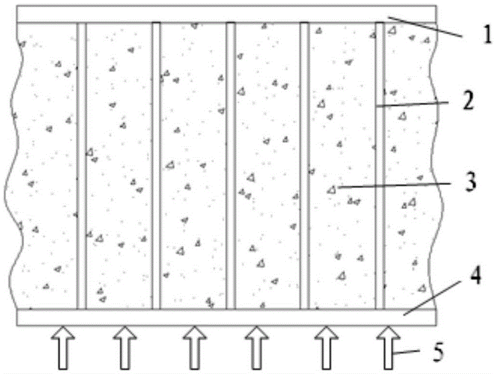
[0033] The present invention proposes an optimal design method for a finned phase change heat storage device in the reentry and return process of a reusable orbital maneuvering vehicle, such as figure 1 As shown, the fin-type phase change heat storage device includes parallel fins 2 installed between the upper cover plate 1 and the lower bottom plate 4 and phase change heat storage materials 3 filled between the fins. The direction of heat flow 5 Such as figure 1 .

[0034] Such as figure 2 As shown, an optimal design method for a fin-type phase change heat storage device, the steps are as follows:

[0035] (1) When designing a phase change heat storage device, it is first necessary to sort out the design input conditions. According to the relevant requirements for the design of the finned phase change heat storage device during the re-entry and return process of the reusable orbital maneuvering vehicle, the input conditions mainly involved in the present invention include...


PUM


Abstract

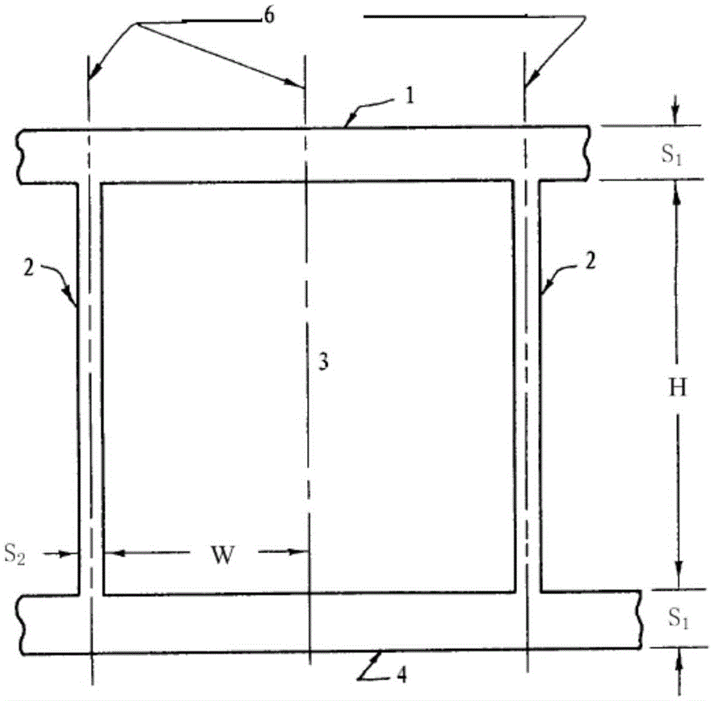
An optimizing and designing method of a rib type phase change heat storage device includes the steps of firstly, determining the heat flow density of the lower base plate of the rib type phase change heat storage device and the section surface density upper limit of the same; secondly, taking the part, along the height direction and between the symmetrical shaft, of two adjacent ribs of the rib type phase change heat storage device as the typical analysis unit, and taking half of the typical analysis unit as one analysis unit; thirdly, building a two-dimensional heat transfer model of the one analysis unit; fourthly, initializing W, calculating the temperature difference when the heat storage materials are totally melted according to the two-dimensional heat transfer model, and optimizing to achieve the minimum temperature different to obtain optimized half distance W between the adjacent ribs; fifthly, calculating the thickness S2 of the ribs according to the optimized W, and determining the section surface density rho of the device, judging whether rho is larger than rho1 or not, if so, increasing the optimized W, and optimizing from the fourth step; or else, designing the rib type phase change heat storage device according to the optimized W and S2.

Description

technical field [0001] The invention relates to an optimal design method of a high-efficiency phase-change thermal storage device, especially for the optimal design of a fin-type phase-change thermal storage device, which is mainly used for the thermal control system design and intermittent Temperature control of working electronics. Background technique [0002] During the reentry and return process of the reusable orbital maneuvering vehicle, it will be affected by strong aerodynamic heating, so that the back temperature of the thermal protection components of the vehicle is extremely high. The interior of the cabin is sealed, so the heat cannot be diffused outwards, and it will also be transmitted to the equipment in the cabin, which will easily lead to failure of the equipment in the cabin. All waste heat is absorbed. [0003] When selecting phase change materials, because paraffin materials have the advantages of high latent heat, low price, stable temperature and che...

Claims


Application Information

Patent Timeline
Patent Type & Authority Patents(China)
IPC IPC(8): G06F17/50
Inventor 王领华王思峰刘欣吕建伟李彦良屈强洪文虎王海英巩萌萌
Owner CHINA ACAD OF LAUNCH VEHICLE TECH
Learn More