
Optimal design method and system for blades of axial flow compressor

An axial flow compressor and optimization design technology, applied in computer-aided design, mechanical equipment, design optimization/simulation, etc., can solve problems such as difficult to give a reasonable distribution

Active Publication Date: 2021-02-23
SHANGHAI JIAO TONG UNIV
View PDF9 Cites 0 Cited by
  • Summary
  • Abstract
  • Description
  • Claims
  • Application Information

AI Technical Summary

Problems solved by technology

However, for the aerodynamic load, it is difficult to give a reasonable distribution along the radial direction at the beginning of the design

Method used


Image

  • Optimal design method and system for blades of axial flow compressor
  • Optimal design method and system for blades of axial flow compressor
  • Optimal design method and system for blades of axial flow compressor

Examples


Embodiment Construction

[0046] The present invention will be described in detail below in conjunction with specific embodiments. The following examples will help those skilled in the art to further understand the present invention, but do not limit the present invention in any form. It should be noted that those skilled in the art can make several changes and improvements without departing from the concept of the present invention. These all belong to the protection scope of the present invention.

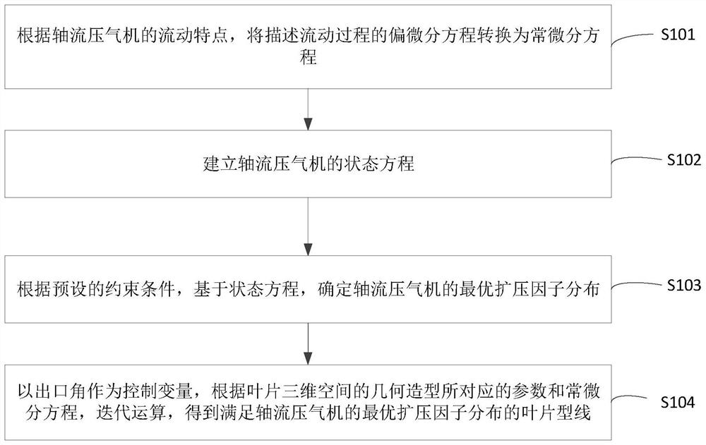
[0047] figure 1 A flow chart of an optimal design method for an axial flow compressor blade provided by the present invention, such as figure 1 As shown, this embodiment may include:

[0048] Step S101 , according to the flow characteristics of the axial flow compressor, convert the partial differential equation describing the flow process into an ordinary differential equation.

[0049] In step S101, it can be assumed that the flow is relatively constant, non-isentropic, the effect of local viscous f...


PUM


Abstract

The invention provides an optimal design method and system for blades of an axial flow compressor, and the method comprises the steps: converting a partial differential equation describing a flow process into an ordinary differential equation according to the flow characteristics of the axial flow compressor; establishing a state equation of the axial flow compressor; determining optimal diffusionfactor distribution of the axial flow compressor based on the state equation according to a preset constraint condition; and taking the outlet angle as a control variable, and performing iterative operation according to parameters corresponding to the geometric modeling of the three-dimensional space of the blade and the ordinary differential equation to obtain the blade profile meeting the optimal diffusion factor distribution of the axial flow compressor. The axial flow compressor blade designed by adopting the method has the characteristics of high efficiency and large stall margin, and issuitable for various design working conditions and variable working conditions.

Description

technical field [0001] The invention relates to the technical field of fluid machinery, in particular to an optimization design method and system for blades of an axial flow compressor. Background technique [0002] Axial flow compressor is the most critical rotating machinery in important industries such as large-scale power generation and military industry. Its work efficiency, reliability and safety have always been the focus of attention of academic circles and business circles. The high efficiency (including design working conditions and variable working conditions) and reliability (long-period trouble-free operation) of the unit play a very important role in the economic benefits of the enterprise. In the blade design of this type of machinery, it is not only necessary to have a high efficiency of a single design condition, but also to have a comprehensive advanced design that can meet multiple design conditions, efficient performance under variable conditions, and a l...

Claims


Application Information

Patent Timeline
Patent Type & Authority Applications(China)
IPC IPC(8): G06F30/17G06F30/27G06F30/28F04D29/38G06F111/04G06F113/08G06F119/14
CPCG06F30/17G06F30/27G06F30/28F04D29/388G06F2111/04G06F2113/08G06F2119/14
Inventor 杨波朱国明周蕊
Owner SHANGHAI JIAO TONG UNIV
Learn More