Al technical title is built by PatSnap Al team. It summarizes the technical point description of the patent document.
A technology of sulfur hexafluoride gas and density relay, which is applied in circuits, electrical switches, electrical components, etc., can solve the problems of difficult to realize display, difficult to popularize and apply, difficult to realize density relay, etc., and achieves good stability, anti-vibration damping and other problems. The effect is obvious and meets the effect of the contact hysteresis
Active Publication Date: 2014-02-19
SHANGHAI ROYE ELECTRICAL CO LTD
View PDF12 Cites 9 Cited by
Summary
Abstract
Description
Claims
Application Information
AI Technical Summary
This helps you quickly interpret patents by identifying the three key elements:
Problems solved by technology
Method used
Benefits of technology
Problems solved by technology
When the Baden tube 6 moves, the sector gear shaft 24 with the movement 2 rotates, so that the adjusting screw rotates and touches the operating arm of the micro switch, and the operating arm is driven to press the movable contact of the switch. When it is rotated to the end face of the adjusting screw When it is perpendicular to the operating arm of the micro switch, the adjustment screw is stuck and cannot be rotated, so it is difficult to realize the full-scale density relay of -0.1 ~ 0.9MPa, especially difficult to realize the display with the initial value of -0.1MPa , it cannot be displayed when vacuuming, and it is difficult to popularize and apply, so innovation is very much needed
Method used
Image
Click on the blue label to locate the original text in one second.
Reading with bidirectional positioning of images and text.
Examples
Embodiment Construction
[0036] In order to better understand the technical solutions of the present invention, specific embodiments will be described in detail below in conjunction with the accompanying drawings.
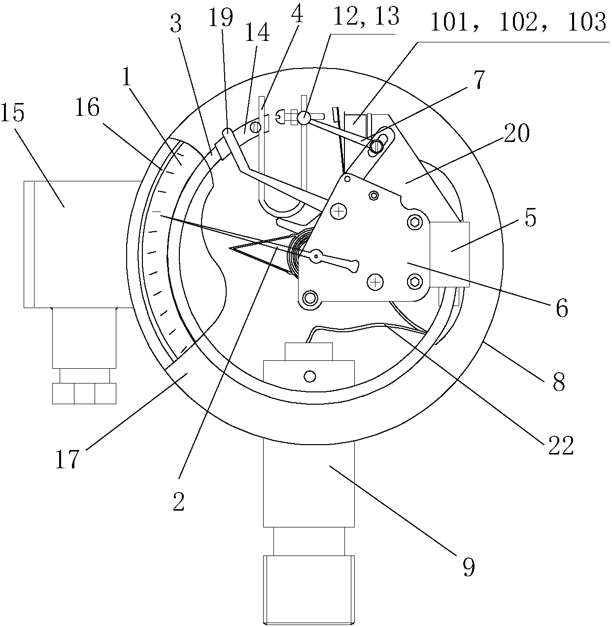
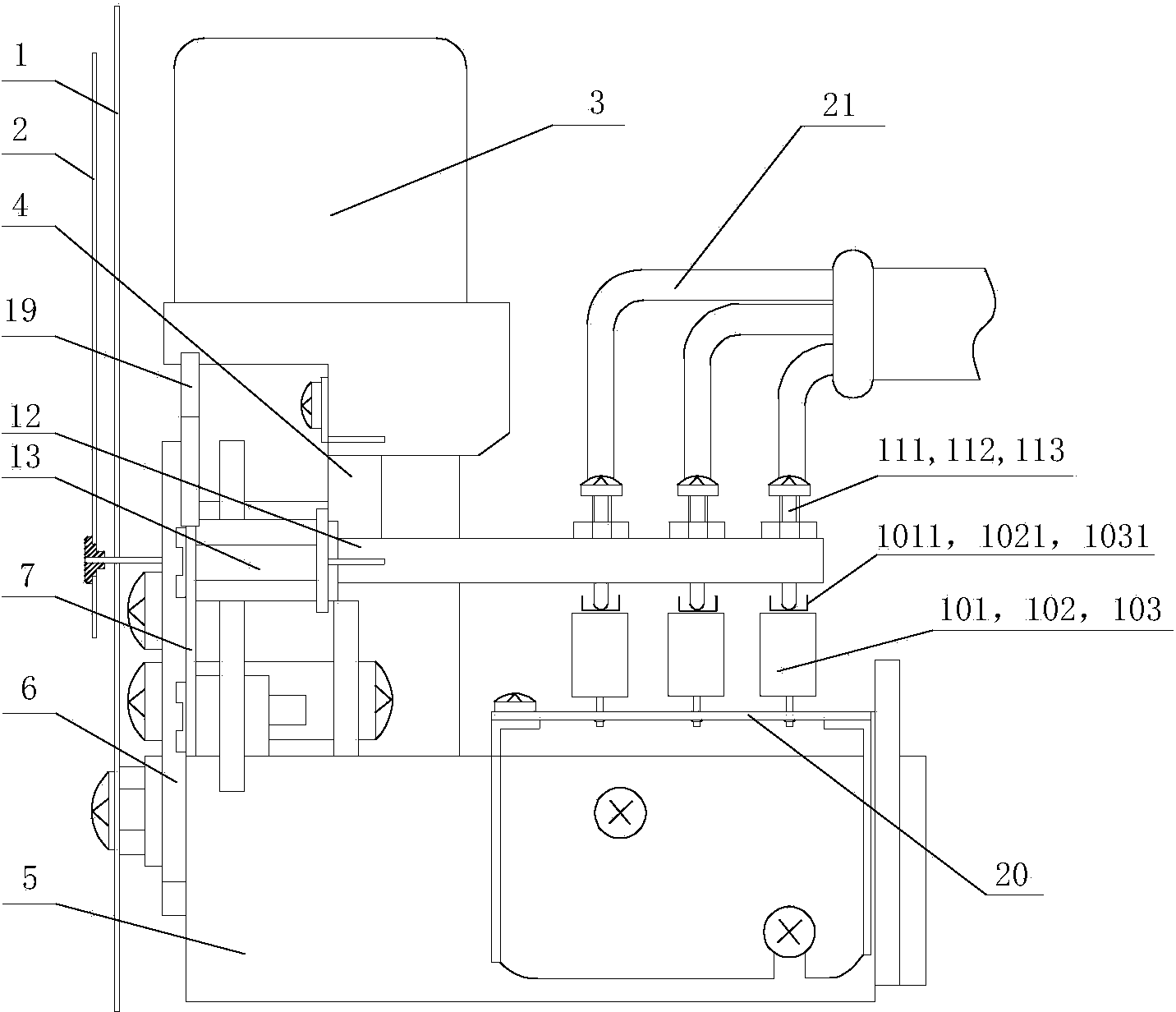
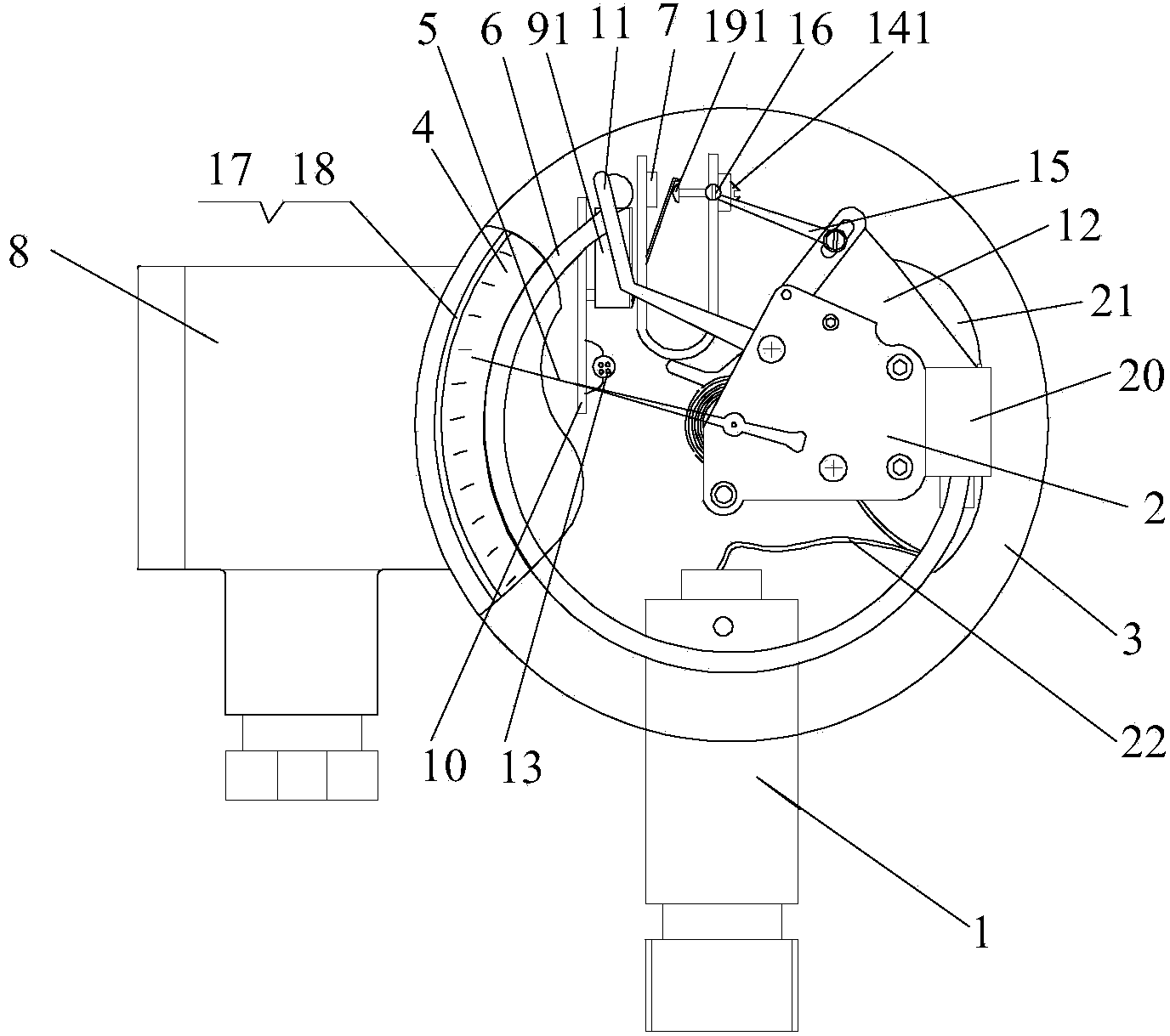
[0037] see Figure 8 to Figure 13 , the first sulfur hexafluoride gas density relay of the present invention is mainly composed of a joint 1, a core 2, a housing 3, a dial 4, a pointer 5, a Baden tube 6, a temperature compensation element 7, a terminal block 8, three Micro switches 91, 92, 93, printed circuit board 10, positioning plate 11, fixed plate 12, electric wire 13, signal adjustment mechanism, connecting rod 15, beam 16, watch glass 17, cover ring 18, base 19, Pipe 20, anti-misoperation mechanism 21, micro switch strengthening mechanism 23, end seat 24 etc. composition. Wherein, the joint 1 is fixed on the housing 3, and the movement 2 is fixed on the base 19; one end of the Baden tube 6 is welded on the base 19 and communicates with it, and the other end is connected to the temp...
PUM
Abstract
The invention discloses a sulfur hexafluoride gas density relay. According to the sulfur hexafluoride gas density relay, the shock resistance performance is higher, the contact point contact and electrical performance of a signal generator is better, the service life is long, and the precision is high. The sulfur hexafluoride gas density relay comprises a shell, a base, an end base, a Bourdon tube, a temperature compensating component, a machine core, a signal conditioning mechanism and a plurality of microswitchs, wherein the end base, the Bourdon tube, the temperature compensating component, the machine core, the signal conditioning mechanism and the microswitchs are arranged in the shell. The sulfur hexafluoride gas density relay is characterized by further comprising a misoperation preventing mechanism corresponding to contact operating arms of the microswitchs. The misoperation preventing mechanism comprises a fixing base, a rotary shaft, a rotary piece and a deflector rod, wherein the deflector rod abuts against the contact operating arm of each microswitch. When the gas density relay is impacted or vibrated, the deflector rod of the malfunction preventing mechanism swings through the rotary piece and deflects the contact operating arm of each microswitch to the pressure increasing direction, so that the signal generator is far away from the position where a misoperation occurs, the signal conditioning mechanism is prevented from mistakenly triggering the signal generator when the gas density is normal, and the shock resistance performance of the density relay is greatly improved.
Description
technical field [0001] The invention relates to a sulfur hexafluoride gas density relay. Background technique [0002] At present, oil-free gas density relays with micro switches as contacts are generally used to monitor the gas density of sulfur hexafluoride in electrical equipment, such as Chinese patents or patent applications 200510110648.5, 200520045890.4, 200520045891.9, 200520115321.2, 200610023139.3, Gas density relays disclosed in 200610118940.6, 200810201462.4, 200910195174.7, 201020190271.5 and 201010171798.8 (such as figure 1 and figure 2 As shown) generally includes dial 1, pointer 2, Baden tube 3, temperature compensation element 4, base 5, movement with display amplification mechanism 6, connecting rod 7, housing 8, joint 9, micro switch 101, 102, 103, adjusting parts 111, 112, 113, contact operating arm 12, connecting arm 13, end seat 14, wiring seat 15, watch glass 16, cover case 17, printed circuit board 18, positioning plate 19, fixing Plate 20 , wire ...
Claims
Application Information
Patent Timeline
Application Date:The date an application was filed.
Publication Date:The date a patent or application was officially published.
First Publication Date:The earliest publication date of a patent with the same application number.
Issue Date:Publication date of the patent grant document.
PCT Entry Date:The Entry date of PCT National Phase.
Estimated Expiry Date:The statutory expiry date of a patent right according to the Patent Law, and it is the longest term of protection that the patent right can achieve without the termination of the patent right due to other reasons(Term extension factor has been taken into account ).
Invalid Date:Actual expiry date is based on effective date or publication date of legal transaction data of invalid patent.