Rapid locking-disengaging coupling element

A technology of connector plugs and connector sockets, which is applied in the direction of connection, two-part connection devices, parts of connection devices, etc., and can solve problems such as inability to realize fast plug-in and separation, long operation time of connectors, and complex structure.

Active Publication Date: 2014-02-19
ZHEJIANG ZHONGHANG ELECTRONICS
View PDF6 Cites 16 Cited by
  • Summary
  • Abstract
  • Description
  • Claims
  • Application Information

AI Technical Summary

Problems solved by technology

[0003] The purpose of the present invention is to solve the problems of long operating time of the prior art connectors, inability to realize fast insertion and separation and high production cost of complex structure, and to provide a connector plug with simple structure, convenient operation, fast locking and separation seat

Method used


Image

  • Rapid locking-disengaging coupling element
  • Rapid locking-disengaging coupling element
  • Rapid locking-disengaging coupling element

Examples


Embodiment 1

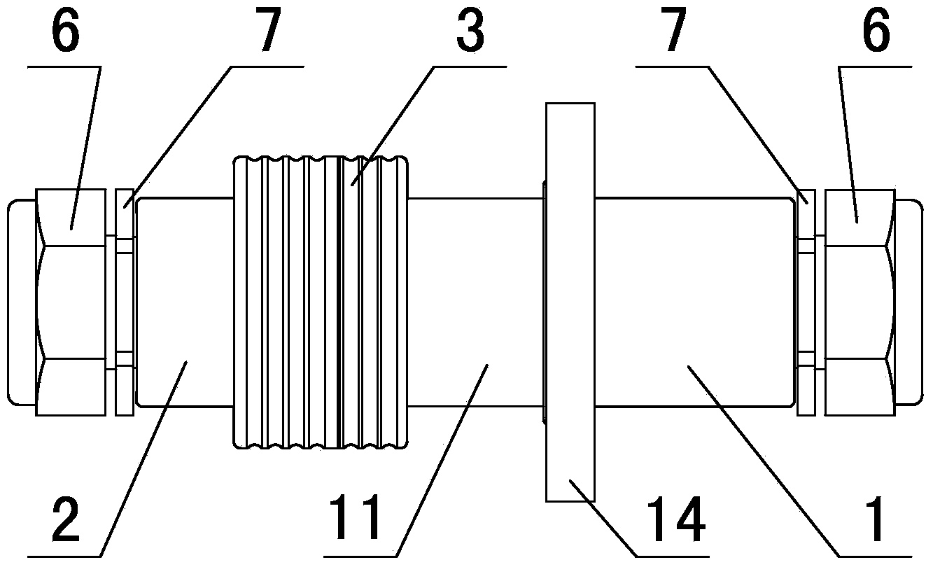
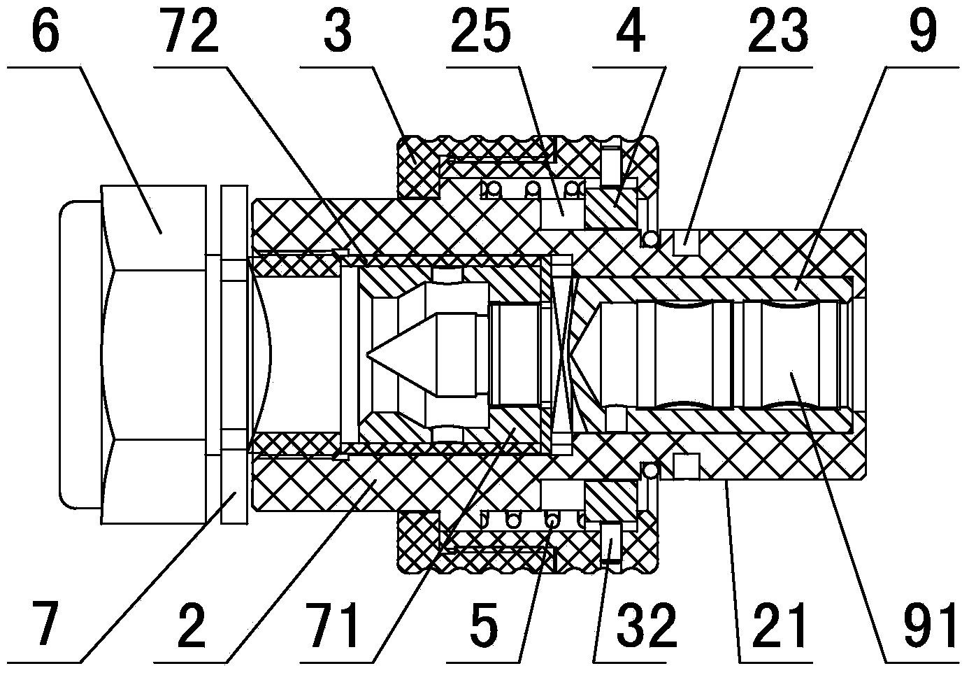
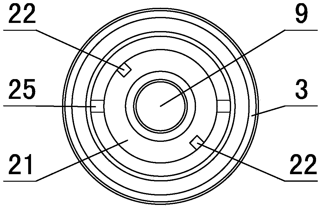
[0028] in such as figure 2 image 3 In the shown embodiment 1, a quick-locking and detaching connector plug, the insertion part 21 of the plug 2 is cylindrical, and an L-shaped groove is provided on the outer wall of the insertion part. The L There are 2 shaped grooves, which are evenly distributed on the outer wall of the plug socket, and the L-shaped grooves include axially arranged straight grooves 22 and circumferentially arranged transverse grooves 23 (see Figure 4 ), the central angle corresponding to the radial center line at both ends of the transverse groove is 45 degrees, one end of the straight groove communicates with the front end of the socket, the rear end of the socket is provided with a convex ring 24, and the socket is close to The position of the protruding ring is provided with a sealing groove, and a sealing ring is provided in the sealing groove; the protruding ring is provided with axially arranged positioning grooves 25, and there are two positioning...

Embodiment 2

[0032] A quick-locking, detachable connector socket, including a pluggable plug and a socket, the front part of the plug is a cylindrical insertion part, and the front part of the socket is a cylindrical front part Housing, the inner diameter of the front housing is adapted to the outer diameter of the socket part, and the outer wall of the socket part is provided with an L-shaped groove, and the L-shaped groove includes a straight groove arranged in the axial direction and a transverse groove arranged in the circumferential direction. slot, the straight slot communicates with the front end face of the socket, and the inner wall of the front housing is protruded with a staple matching the L-shaped slot; the front end of the front housing is provided with a keyway for insertion The rear end of the part is provided with a protruding ring, the outer diameter of the protruding ring is adapted to the outer diameter of the front housing, the front end of the protruding ring is provid...


PUM


Abstract

The invention discloses a rapid locking-disengaging coupling element. L-shaped grooves are formed in the outer wall of a cylindrical plug-in portion of a plug, clamping screws are convexly arranged on the inner wall of the cylindrical front shell of a plug-in base, positioning grooves are formed in an protruding ring at the rear end of the plug-in portion, key grooves are formed in the front end of the plug-in base, a blocking ring is convexly arranged at the rear end of the protruding ring, the periphery of the blocking ring is sleeved with a sliding sleeve, a locking sleeve is arranged between the sliding sleeve and the protruding ring, key strips are arranged in the locking sleeve, and a spring is arranged between the locking sleeve and the blocking ring. When the plug and the plug-in base are in the locking state, the clamping screws are located at the tail end of the L-shaped grooves, the front portions of the key strips on the plug are located in the key grooves in the plug-in base, and the rear portions of the key strips are located in the positioning grooves in the plug. The rapid locking-disengaging coupling element is simple in structure, convenient to operate, capable of achieving rapid locking and disengaging of a connector, and high in use value.

Description

technical field [0001] The invention relates to a connector, in particular to a fast locking and separating connector socket. Background technique [0002] When the connectors in the prior art are plugged in, the screw fastening method is generally used to realize the tight plugging of the connector socket and the plug. This screw connection method has a simple structure and is convenient to process, but the operation time of this structure is time-consuming. It is too long to realize the fast insertion and separation of the socket and plug, and it is easy to get stuck between the threads after a long time of use and it is difficult to open it. It cannot be used on devices that require quick insertion and separation. The publication date is October 10, 2012, and the Chinese patent document with the publication number CN 202487877 U discloses a pull-off, self-locking electrical connector, which mainly includes a plug and a socket; the plug mainly includes a housing, a jack c...

Claims


Application Information

Patent Timeline
Patent Type & Authority Applications(China)
IPC IPC(8): H01R13/627H01R24/00
Inventor 王吉国
Owner ZHEJIANG ZHONGHANG ELECTRONICS
Why Eureka
Try Eureka