Resonance control circuit and electromagnetic heating device

A resonant circuit and resonant control technology, applied in the direction of induction heating device, induction heating, induction heating control, etc., can solve the problem of high output power

Active Publication Date: 2014-02-19
MIDEA GRP CO LTD +1
View PDF9 Cites 22 Cited by
  • Summary
  • Abstract
  • Description
  • Claims
  • Application Information

AI Technical Summary

Problems solved by technology

[0002] At present, household induction cookers are generally designed as a single coil. Even multi-coil induction cookers are only for the purpose of achieving different heating areas. High output power

Method used


Image

  • Resonance control circuit and electromagnetic heating device
  • Resonance control circuit and electromagnetic heating device
  • Resonance control circuit and electromagnetic heating device

Examples


Embodiment approach 1

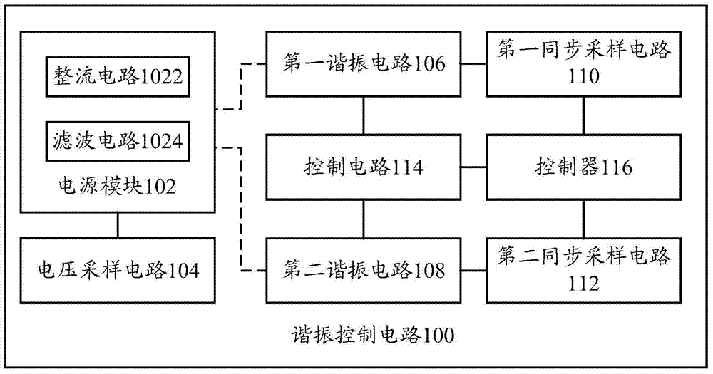
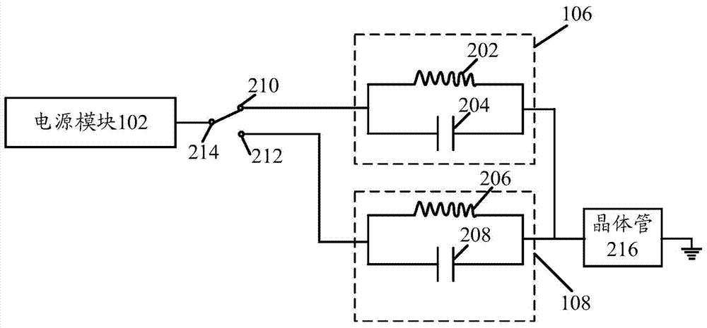
[0056] like Figure 2A as shown, figure 1 The first resonant circuit 106 shown in includes: a first coil 202; and a first capacitor 204 connected in parallel with the first coil 202; figure 1 The second resonant circuit 108 shown in includes: a second coil 206; and a second capacitor 208 connected in parallel with the second coil 206; the first end of the first resonant circuit 106 is connected to the second resonant circuit The first end of 108 is connected with transistor 216, and the second end of transistor 216 is grounded figure 1 The control circuit 114 shown in can control the second end of the first resonant circuit 106 or the second end of the second resonant circuit 108 to be connected to the power module.

[0057]According to the resonant control circuit of the embodiment of the present invention, the first resonant circuit 106 and the second resonant circuit 108 have a common end, that is, one end connected to the power tube 216 respectively, and the second reson...

Embodiment approach 2

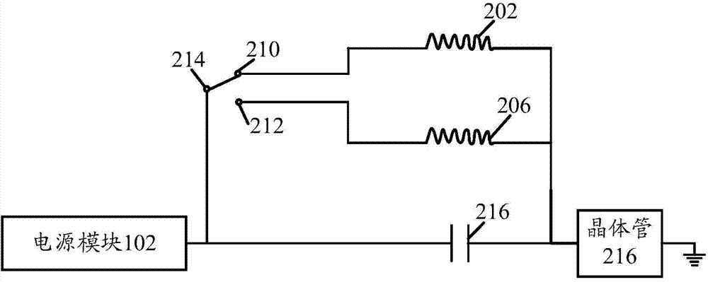
[0061] like Figure 2B As shown, the first resonant circuit 106 ( Figure 2B not marked) and the second resonant circuit 108 ( Figure 2B not marked in ) has a common capacitor 216, the first end of the common capacitor 216 is connected to the first end of the power transistor 216, the second end of the transistor 216 is grounded, and the second end of the common capacitor 216 connected to the power module 102; the first resonant circuit 106 also includes: a first coil 202, the first end of the first coil 202 is connected to the first end of the common capacitor 216; the second The resonant circuit 108 also includes: a second coil 206, the first end of the second coil 206 is connected to the first end of the common capacitor 216; the control circuit 114 can control the second coil 202 of the first coil 202 end or the second end of the second coil 206 is connected to the second end of the resonant capacitor.

[0062] According to the resonant control circuit of the embodimen...


PUM


Abstract

The invention provides a resonance control circuit and an electromagnetic heating device. The resonance control circuit comprises a power source module, a voltage sampling circuit, a first resonance circuit, a second resonance circuit, a control circuit and a controller. The voltage sampling circuit is used for sampling voltage in the power source module so that the sampled voltage can be obtained; the control circuit is used for controlling the first resonance circuit or the second resonance circuit to be connected with the power source module so that resonance of the first resonance circuit or the second resonance circuit can be achieved; the controller is respectively connected with an output end of the voltage sampling circuit and an input end of the control circuit and used for sending a control signal to the control circuit according to the relationship between the sampled voltage and the preset voltage value. According to the technical scheme, resonance of a circuit is achieved through the different resonance circuits, and therefore it is guaranteed that the electromagnetic heating device can achieve high-power output at high voltage and low voltage.

Description

technical field [0001] The invention relates to the technical field of electrical appliances with electromagnetic induction, in particular to a resonance control circuit and an electromagnetic heating device. Background technique [0002] At present, household induction cookers are generally designed as a single coil. Even multi-coil induction cookers are only for the purpose of achieving different heating areas. Output high power. [0003] Therefore, how to ensure that the electromagnetic heating device can realize high-power heating under high and low pressure has become a technical problem to be solved urgently. Contents of the invention [0004] The present invention aims to solve at least one of the technical problems existing in the prior art or related art. [0005] Therefore, an object of the present invention is to provide a resonant control circuit capable of ensuring high power output under both high and low voltage conditions. [0006] Another object of the ...

Claims


Application Information

Patent Timeline
Patent Type & Authority Applications(China)
IPC IPC(8): H05B6/06H05B6/12
Inventor 曾燕侠陈永顺谢波
Owner MIDEA GRP CO LTD
Why Eureka
Try Eureka