

Air source power system
A power system and air engine technology, applied in the direction of machines/engines, mechanical equipment, etc., can solve the problems of insufficient utilization of compressed air, bulky, increased operating costs, etc., and achieve the effect of energy reuse
- Summary
- Abstract
- Description
- Claims
- Application Information
AI Technical Summary
Problems solved by technology
Method used
Image

Examples
Embodiment 1
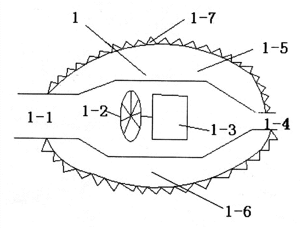
[0042] Such as Figure 1-2 As shown, this embodiment is used to illustrate the working principle and process of the fully sealed circulating air energy power system.
[0043]The working principle is as follows: use the ordinary compressor to inflate the tires to fill the inner space of the sealed cycle of the fully sealed cycle air energy power system with appropriate compressed gas. When the high-pressure fan 1 is working, the outlet 1-4 of the high-pressure fan 1 will generate high-pressure gas , the air inlet 1-1 of the high-pressure fan 1 produces low pressure, and a pressure difference appears in the sealed inner circulation space. The airflow circulates continuously. During this process, the sealed internal circulation design makes full use of the physical characteristics of the airflow to continuously obtain energy from the kinetic energy of the air movement, so as to achieve the purpose of low power input and high power output.
[0044] Its working process is as follo...
Embodiment 2
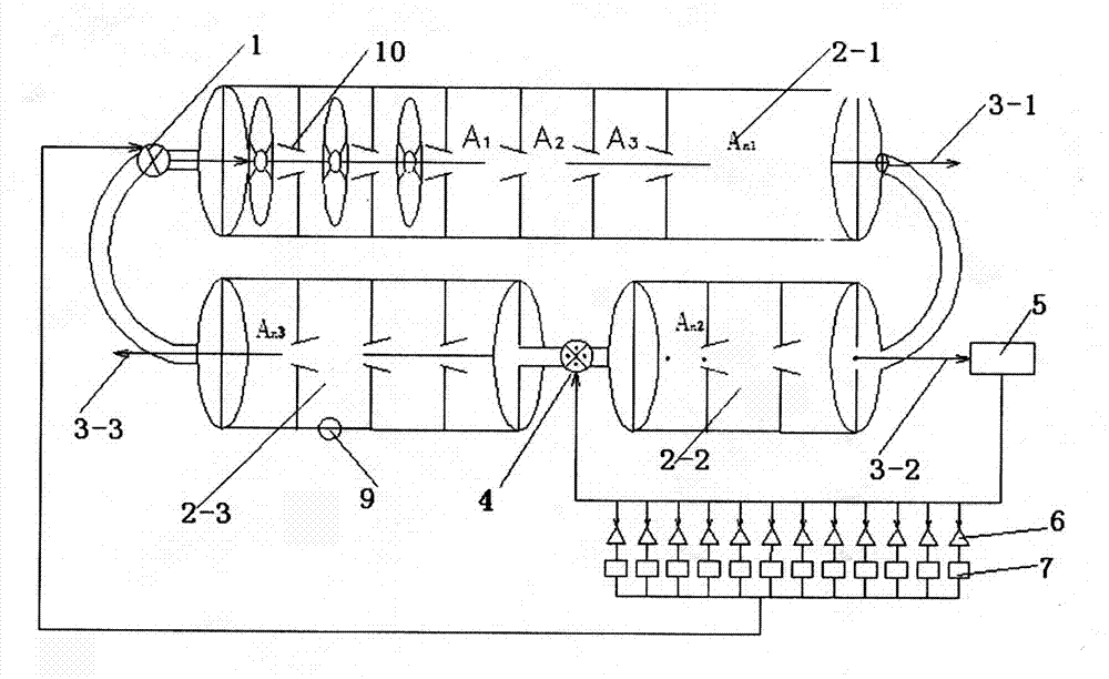
[0056] Such as Figure 8 As shown, the working principle of the semi-sealed circulating air energy power system is described with this embodiment. The semi-sealed circulating air energy power system includes a high-pressure gas storage 11, the first-fourth air engine working groups 2-1, 2-2, 2-3, 2-4, a booster fan 4, an alternator 5, and a power output Axis 3-2, air pressure control throttle valve 12, air nozzle 13. Wherein the high-pressure gas storage 11 is connected to the air inlet of the first air engine working group 2-1, wherein the air inlet of the booster blower 4 is separated from the exhaust port of the fourth air engine working group 2-4 by an appropriate space distance, and in the same horizontal direction, the horizontal space is correspondingly installed, and the power output shaft 3-2 of the second air engine working group 2-2 outputs mechanical energy, wherein the alternator 5 is powered by the third air engine working group The mechanical energy output by ...
Embodiment 3
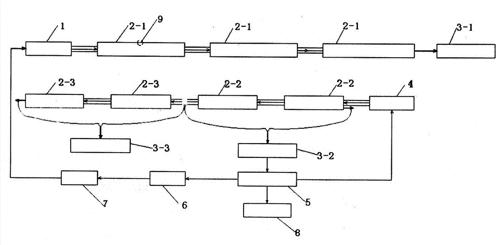
[0065] On the basis of Embodiment 1 and Embodiment 2, an incremental air energy power system is formed, such as Figure 13 , firstly, the mechanical energy output is generated by the high-pressure fan of the first group of fully sealed circulating air energy power system. The output of mechanical energy generated under the action will drive the third group of fully sealed circulating air energy power system through the gearbox, which can be increased in turn, and part of the mechanical energy of the second group of fully sealed circulating air energy power system is used to generate electricity, and the generated electric energy is semi-sealed The air booster of the type system provides power. The whole process, from the original small external power input to the incremental energy increase from small to several times, dozens of times..., even tens of thousands of times, is not limited by space. conditions for power generation.
PUM
 Abstract
Description
Claims
Application Information