Supporting device for frame structure
A technology of supporting device and frame structure, applied in building components, building structure, earthquake resistance, etc., can solve problems such as affecting the use of building space
- Summary
- Abstract
- Description
- Claims
- Application Information
AI Technical Summary
Problems solved by technology
Method used
Image
Examples
Embodiment
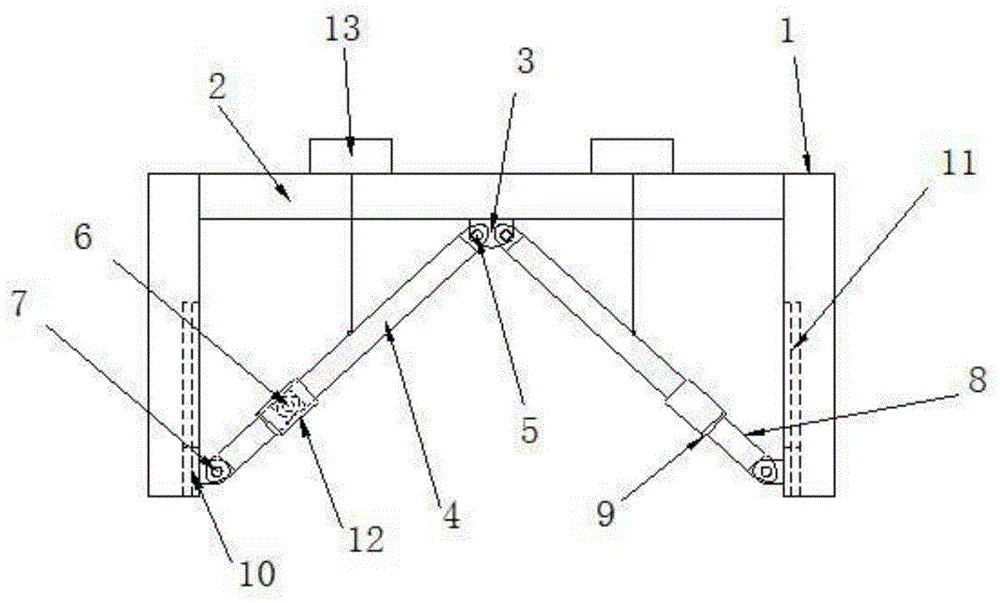
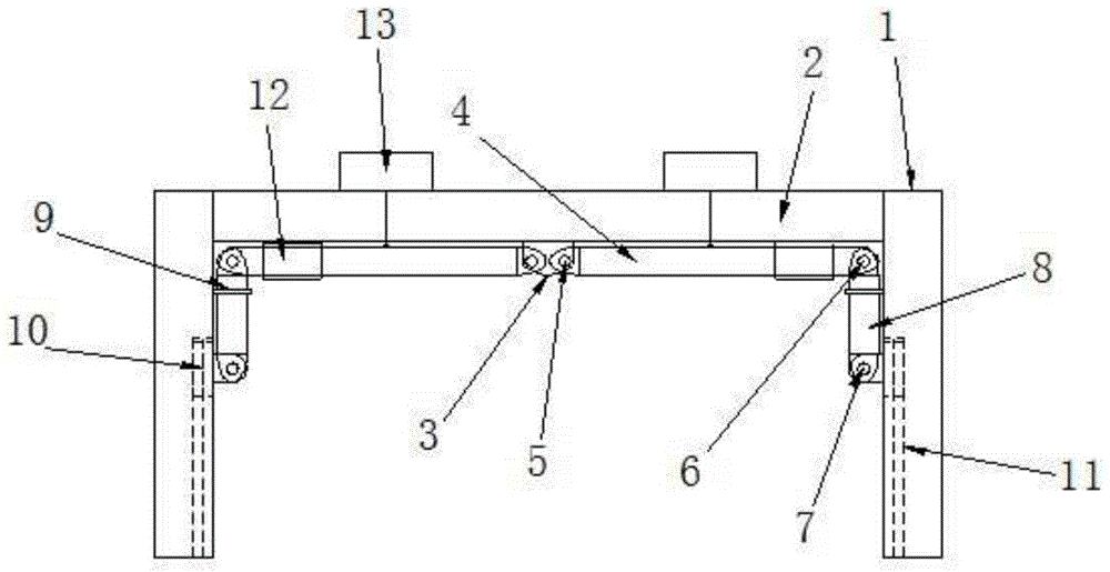
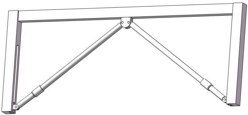
[0018] figure 2 It is a retracted state of a support device for a frame structure, including frame column 1, frame beam 2, fixed hinge support 3, upper support bar 4, pivot pin a5, pivot pin b6, pivot pin c7, lower support Rod 8, snap ring 9, slider 10, chute 11, sleeve 12, pneumatic hoist 13; the frame beam 2 rests on the frame column 1; the fixed hinge support 3 is located at the mid-span position of the frame beam 2 , connected with the upper support rod 4 through the pivot pin a5; the upper support rod 4 and the lower support rod 8 are connected through the pivot pin b6; the lower support rod 8 is provided with a snap ring 9; the lower support The rod 8 is connected to the slider 10 through the shaft pin c7; the slider 10 slides in the chute 11; the chute 11 is located in the frame column 1; the sleeve 12 is sleeved on the upper support rod 4; The hook of the pneumatic hoist 13 hooks the upper supporting rod 4 .
[0019] The length of the upper support bar 4 is equal to...
PUM
 Abstract
Description
Claims
Application Information
 - R&D
- Intellectual Property
- Life Sciences
- Materials
- Tech Scout
- Unparalleled Data Quality
- Higher Quality Content
- 60% Fewer Hallucinations
Browse by: Latest US Patents, China's latest patents, Technical Efficacy Thesaurus, Application Domain, Technology Topic, Popular Technical Reports.
© 2025 PatSnap. All rights reserved.Legal|Privacy policy|Modern Slavery Act Transparency Statement|Sitemap|About US| Contact US: help@patsnap.com


