Molten pool monitoring device for laser processing process

A laser processing and monitoring device technology, which is applied in the direction of optical testing for flaws/defects, can solve problems such as low processing quality and prone to defects, and achieve the effect of avoiding mutual occlusion, false detection and harm to monitoring personnel

Active Publication Date: 2014-02-26
NANJING HUIRUI PHOTOELECTRIC TECH CO LTD
View PDF4 Cites 21 Cited by
  • Summary
  • Abstract
  • Description
  • Claims
  • Application Information

AI Technical Summary

Problems solved by technology

[0005] The invention provides a molten pool monitoring device used in laser processing to replace manual observation and monitoring, and solve

Method used


Image

  • Molten pool monitoring device for laser processing process
  • Molten pool monitoring device for laser processing process
  • Molten pool monitoring device for laser processing process

Examples


Embodiment 1

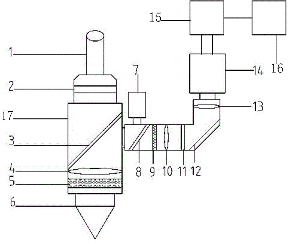
[0028] like figure 2 As shown, the embodiment of the present invention provides a molten pool monitoring device used in the laser processing process. In the laser processing process, the laser beam 1 passes through the collimating mirror 2, the focusing mirror 4, and the protective mirror in the laser head 17 in sequence. 5 and the nozzle 6 reach the surface of the substrate 19 or the cladding layer 20 to form a molten pool 18 on the surface of the substrate 19 or the cladding layer 20, and the molten pool monitoring device includes a beam splitter 3, a lens module and an acquisition control system, The beam splitter 3 is arranged between the collimating mirror 2 and the focusing mirror 4 in the laser head 17, and is fixedly arranged at an angle of 45° with the laser beam 2, and the beam splitter 3 makes the laser beam 1 It is located on the same axis as the visible light reflected from the melting pool 18, and its incident angle differs by 180°. The visible light is focused ...

Embodiment 2

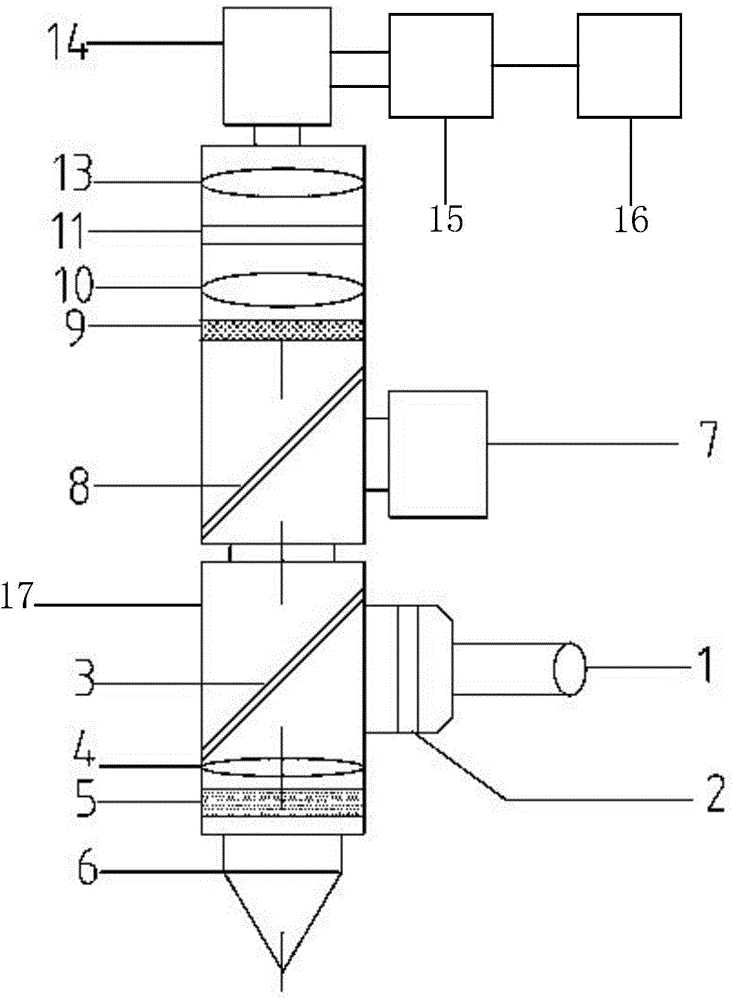
[0036] like image 3 As shown, compared with Embodiment 1, the technical features of the embodiment of the present invention are basically the same, and the only difference is that the laser beam 7 enters the laser head 17 from one side of the laser head 17, and the lens The module is located above the laser head 17, the beam splitter 3 reflects the laser beam 1 to make it reach the surface of the substrate 19 or the cladding layer 20, and transmits the visible light reflected from the molten pool 18 to make it into the lens module.

[0037] Combining Embodiment 1 and Embodiment 2, it can be concluded that the molten pool monitoring device provided by the present invention is applicable to laser heads 17 with different structures, which shows that the molten pool monitoring device has strong adaptability.

[0038] To sum up, the melt pool monitoring device for laser processing provided by the embodiment of the present invention makes the imaging optical path and the laser opt...


PUM


Abstract

The invention provides a molten pool monitoring device for a laser processing process. In the laser processing process, laser beams sequentially pass through a collimating mirror, a focus lens, a protective glass and a nozzle in a laser head to reach the surface of a base material or a cladding layer, so that a molten pool is formed on the surface of the base material or the cladding layer. The molten pool monitoring device comprises a beam splitter, a lens module and an acquisition control system, wherein the beam splitter is arranged between the collimating mirror and the focus lens in the laser head, and the beam splitter and the laser beams are fixedly arranged in an angle of 45 degrees. According to the molten pool monitoring device, an imaging light path and a laser light path are positioned on the same axis through the beam splitter, the difference of incidence angles is 180 degrees, and shielding between the light paths is avoided, so that the molten pool monitoring device can be used for any processing path. Moreover, real-time imaging can be realized in real time and various information of the molten pool is monitored through the lens module and the acquisition control system along with the laser head, and false detection possibly brought by manual observation and monitoring and injury of the monitoring personnel are avoided.

Description

technical field [0001] The invention relates to the field of laser processing, in particular to a molten pool monitoring device used in the laser processing process. Background technique [0002] Laser material processing and manufacturing refers to the process of melting externally added metal or non-metallic materials through laser beams, and forming a cladding layer after the materials solidify on the surface of the substrate, such as figure 1 As shown, the laser beam 1 passes through the laser head 17 and reaches the substrate 19 or the cladding layer 20 to form a molten pool 18 . Applications of laser processing mainly include rapid prototyping, cladding and repair. Compared with traditional mechanical processing or arc welding, laser processing has unique advantages and broad application prospects. [0003] However, the existing laser processing technology has great instability. The main reasons include the complexity of the mechanism of laser and material interacti...

Claims


Application Information

Patent Timeline
IPC IPC(8): G01N21/95
Inventor 齐欢杨艳
Owner NANJING HUIRUI PHOTOELECTRIC TECH CO LTD
Why Eureka
Try Eureka