Electrical capacitance tomography sensor used in submerged environment

A sensor and environment technology, applied in the direction of material capacitance, etc., can solve the problem of no sensor, and achieve the effect of expanding the application field

Inactive Publication Date: 2014-02-26
NORTH CHINA ELECTRIC POWER UNIV (BAODING)
View PDF5 Cites 33 Cited by
  • Summary
  • Abstract
  • Description
  • Claims
  • Application Information

AI Technical Summary

Problems solved by technology

For the condensation section cooled by liquid working fluid, due to the limitation of the condensation

Method used


Image

  • Electrical capacitance tomography sensor used in submerged environment
  • Electrical capacitance tomography sensor used in submerged environment
  • Electrical capacitance tomography sensor used in submerged environment

Examples


Embodiment Construction

[0020] The preferred embodiments will be described in detail below in conjunction with the accompanying drawings. It should be emphasized that the following description is only exemplary and not intended to limit the scope of the invention and its application.

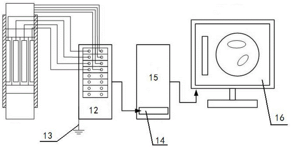
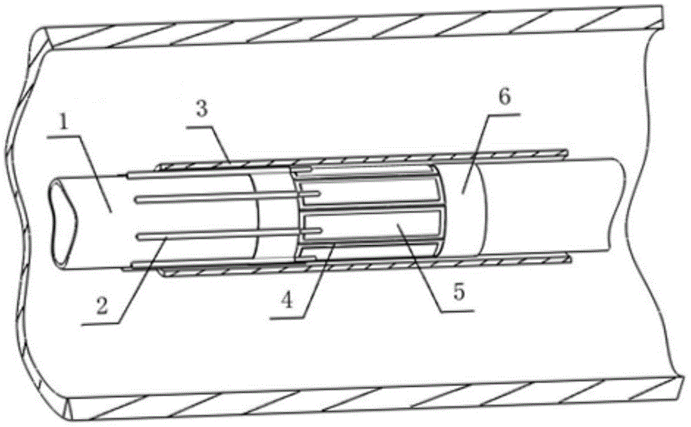
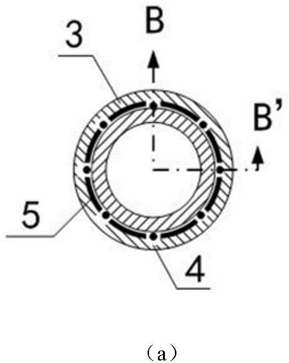
[0021] figure 1 The connection diagram of the sensor provided by the present invention. figure 1 Among them, the sensor includes a two-phase flow distribution measurement electrode array, an electrode end annular shielding electrode 6, an isolation electrode 4 between electrodes, a sensor water-insulating layer 3 and a signal transmission cable 2; the two-phase flow distribution measurement electrode array includes N measurement electrodes 5. The signal transmission cable includes a cable core and a shielding wire mesh;

[0022] Wherein, the inter-electrode isolation electrode 4 is connected to the electrode-end annular shielding electrode 6, drawn out via the shielding wire mesh of the signal transmission cable, and...


PUM


Abstract

The invention discloses an electrical capacitance tomography sensor used in a submerged environment, which belongs to the field of designing of sensors. The sensor comprises a two-phase flow distribution measurement electrode array, an annular-electrode tip shielding electrode, inter-electrode isolation electrodes, a sensor water isolating layer and signal transmission cables, wherein the two-phase flow distribution measurement electrode array comprises N measurement electrodes, and each of the signal transmission cables comprises a cable core and a shielding silk screen. According to the invention, a shielding case structure out of the a traditional electrical capacitance tomography sensor is discarded, an insulating heat-conduction material is used to enclose the measurement electrode array in the outer wall surface of a measurement pipe section, so the electrical capacitance tomography sensor can be placed in the submerged environment, an effective detection means is provided for two-phase distribution of steam and liquid in a heat convection area, formation and development of a liquid film, flow pattern monitoring, etc., and the application field of electrical capacitance tomography technology is effectively broadened.

Description

technical field [0001] The invention belongs to the field of sensor design, and in particular relates to an electric capacitance tomography sensor applied to an underwater environment. Background technique [0002] Using liquid working fluid as the cooling medium, convective heat transfer involving phase change of the cooled medium is a common problem in the field of heat transfer. In the process of heat transfer, it is accompanied by a phase change process. For example: heat exchange in the condensing section of a heat pipe, heat exchange between steam and the outer wall of the tube in the condenser and regenerator of a power plant. Condensation heat transfer is divided into bead condensation and film condensation. The formation of bead condensation is difficult and not durable. In most cases, the condensation heat transfer is film condensation. Different liquid film thicknesses and liquid film motion states greatly affect its heat transfer characteristics. Many factors ...

Claims


Application Information

Patent Timeline
IPC IPC(8): G01N27/22
Inventor 韩振兴李惊涛李志宏刘石王冬骁王飞
Owner NORTH CHINA ELECTRIC POWER UNIV (BAODING)
Why Eureka
Try Eureka