Design method of scramjet fuel injection system
A fuel injection system, scramjet technology, applied in computing, special data processing applications, instruments, etc., can solve the difficulty of hypersonic inlet outlet flow, lack of understanding of the internal flow field of the combustion chamber, and lack of information transmission and feedback mechanisms To achieve the effect of enhancing fuel injection and blending capabilities, strengthening the degree of integrated design, and improving overall performance
- Summary
- Abstract
- Description
- Claims
- Application Information
AI Technical Summary
Problems solved by technology
Method used
Image
Examples
Embodiment 1
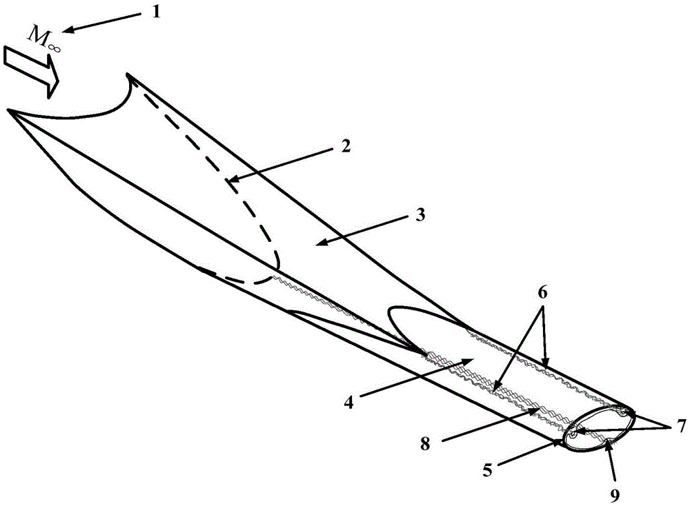
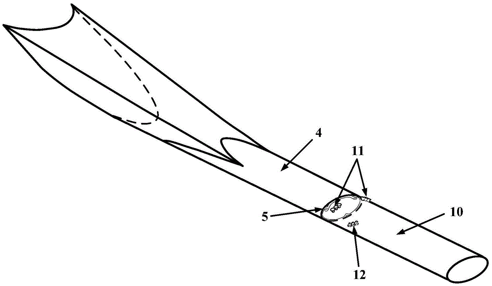
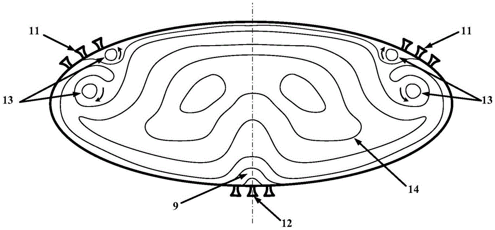
[0041] The outlet of the three-dimensional internal multiplier hypersonic inlet is an ellipse with a length-to-minor axis ratio of 2.5, and the inlet is similar to a V shape. The upstream intake port and the downstream combustion chamber are connected with equal area, and there is no gradual or sudden transition of geometric area. There are obvious corner vortex characteristics and low energy / low speed zones at the upper left and right corners and the bottom of the inlet, respectively, and propagate to the downstream combustion chamber (such as figure 1 ). 3 nozzles are evenly distributed along the circumferential direction on the left and right upper corners and bottom of the combustion chamber (e.g. figure 2 with 4 ). The flow field of the inlet outlet section is as image 3 As shown, the fuel blending effect is obvious.
Embodiment 2
[0043] The outlet of the hypersonic three-dimensional internal wave multiplier inlet is an ellipse with a length-to-minor axis ratio of 2.5, and the inlet shape is similar to a V shape. The upstream intake port and the downstream combustion chamber are connected with equal area, and there is no gradual or sudden transition of geometric area. There are obvious corner vortex characteristics and low energy / low speed zones at the left and right upper corners and bottom of the inlet, respectively, and propagate to the downstream combustion chamber (such as figure 1 ). At the left and right upper corners and bottom of the combustion chamber, 5 nozzles are distributed along the flow path of the corner vortex and the low energy / low speed zone (such as Figure 5 with 7 ). The flow field of the inlet outlet section is as Image 6 As shown, the fuel blending effect is obvious.
Embodiment 3
[0045] The outlet of the hypersonic three-dimensional internal wave multiplier inlet is an ellipse with a length-to-minor axis ratio of 2.5, and the inlet shape is similar to a V shape. The upstream intake port and the downstream combustion chamber are connected with equal area, and there is no gradual or sudden transition of geometric area. There are obvious corner vortex characteristics and low energy / low speed zones at the upper left and right corners and the bottom of the inlet, respectively, and propagate to the downstream combustion chamber (such as figure 1 ). At the left and right upper corners and bottom of the combustion chamber, along the flow path of the corner zone vortex and the low energy / low speed zone, 3 nozzles (such as Figure 8 with 10 ). The flow field of the inlet outlet section is as Picture 9 As shown, the fuel blending effect is obvious.
PUM
 Abstract
Description
Claims
Application Information
 - R&D
- Intellectual Property
- Life Sciences
- Materials
- Tech Scout
- Unparalleled Data Quality
- Higher Quality Content
- 60% Fewer Hallucinations
Browse by: Latest US Patents, China's latest patents, Technical Efficacy Thesaurus, Application Domain, Technology Topic, Popular Technical Reports.
© 2025 PatSnap. All rights reserved.Legal|Privacy policy|Modern Slavery Act Transparency Statement|Sitemap|About US| Contact US: help@patsnap.com


