Wireless network and touch-control control-based back edge modulation dimming switch

A technology of wireless network and dimming switch, applied in the field of trailing edge modulation dimming switch, which can solve the problems of potentiometer contact wear, large impact current, failure of SCR conduction, etc., to suppress current impact and increase service life , The effect of convenient remote control

Inactive Publication Date: 2014-02-26
SUNSUN LIGHTING CHINA
View PDF7 Cites 4 Cited by
  • Summary
  • Abstract
  • Description
  • Claims
  • Application Information

AI Technical Summary

Problems solved by technology

[0003] When the power of this kind of lamp is relatively small, the current flowing through the thyristor is too small to keep the thyristor turned on, so that the light cannot be adjusted normally.
The power of LED lamps is relatively small. If this kind of dimmer is used, the dimming range will become smaller, and the lamps will flicker when dimmed to low brightness.
Secondly, when the thyristor is turned on, the AC voltage is not zero, so there will be a relatively large impact current during the turn-on period, and this impact may affect the operation of other equipment in the power grid.
The existing dimmer control method adjusts the conduction time of the thyristor by changing the resistance value of the potentiometer. This adjustment method will have mechanical wear on the contacts of the potentiometer, and the service life is relatively short.
[0004] In addition, in the lighting control, the traditional two-site control method needs to be opened by a single-pole double-throw switch in the two sites, and the switches are connected by 3 wires. The wiring is complicated, and it is difficult to achieve control of more than two sites.
At the same time, most of the traditional switches have no wireless control function and can only be switched on the switch panel. Even if there is a wireless remote control function, it can only be operated by the remote control. If the remote control is damaged or lost, it will affect the user's use.

Method used


Image

  • Wireless network and touch-control control-based back edge modulation dimming switch
  • Wireless network and touch-control control-based back edge modulation dimming switch
  • Wireless network and touch-control control-based back edge modulation dimming switch

Examples


Embodiment Construction

[0024] Below in conjunction with accompanying drawing, technical scheme of the present invention is described in further detail:

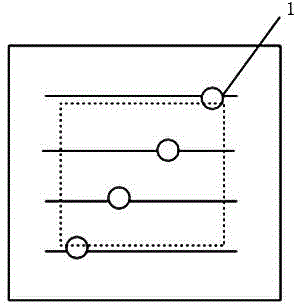
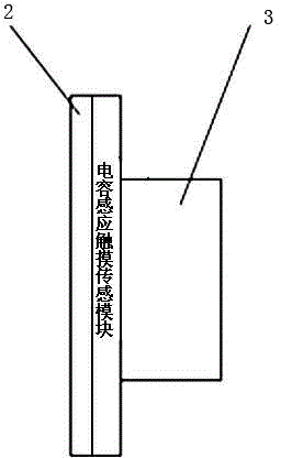
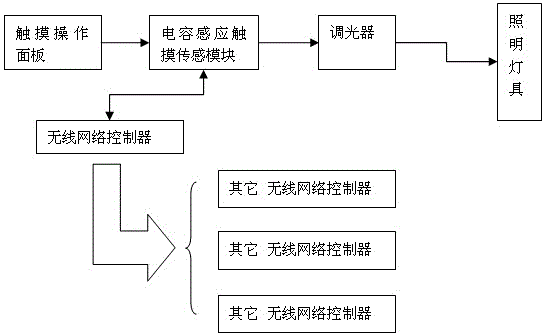
[0025] Physical structure front view and side view of the present invention are respectively as figure 1 , figure 2 As shown, the composition module of the present invention includes a touch operation panel and a pre-embedded box, and the periphery of the touch operation panel is connected with the pre-embedded box to form a structure containing a cavity, and the capacitive sensing touch sensor module is arranged on the back of the touch operation panel; It also includes a dimmer and a wireless network controller connected in sequence, and the dimmer and the wireless network controller are all arranged in the pre-embedded box. The touch operation panel can also be marked with a touch operation area, and an indicator light can be set to facilitate the user's operation. A trailing edge dimming circuit is set in the dimmer to adjust and control the...


PUM


Abstract

The invention discloses a wireless network and touch-control control-based back edge modulation dimming switch. The wireless network and touch-control control-based back edge modulation dimming switch comprises a touch operation panel, a capacitance induction touch sensing module, a pre-embedded box, a dimmer and a wireless network controller; the periphery of the touch operation panel is connected with the pre-embedded box, such that a structure with a cavity arranged inside can be formed; the capacitance induction touch sensing module is arranged at the back surface of the touch operation panel and is connected with the touch operation panel in a closely-fitting manner; the capacitance induction touch sensing module is further connected with the dimmer and the wireless network controller respectively; the dimmer and the wireless network controller are both arranged in the pre-embedded box; the dimmer comprises a back edge dimming circuit arranged inside; and the wireless network controller comprises a Zigbee module. With the wireless network and touch-control control-based back edge modulation dimming switch adopted, the service life of the dimming switch can be prolonged, and remote control can be realized conveniently, impact on a power grid can be reduced, and flicker phenomenon of a silicon controlled rectifier dimming circuit under a small-current working condition can be avoided. The wireless network and touch-control control-based back edge modulation dimming switch is suitable for being applied to the LED lamp control field.

Description

technical field [0001] The invention discloses a trailing edge modulation dimmer switch based on wireless network and touch control, and relates to the technical field of lamp control switches. Background technique [0002] During the use of the lamp, the controllable adjustment of the brightness of the light is an important additional function. Existing dimmers adopt the SCR frontier modulation method, and the user controls the conduction angle of the SCR by rotating the potentiometer to realize the brightness control of the lamp. The working process of leading edge modulation is as follows: 1. Detect the moment when the AC input power voltage is zero; 2. Delay for a period of time (this time is adjusted by the user to rotate the potentiometer); 3. Send a pulse signal to the thyristor to make the controllable Silicon conduction. When the thyristor is turned on, the control signal is removed, and as long as the current flowing through the thyristor is greater than a certai...

Claims


Application Information

Patent Timeline
Patent Type & Authority Applications(China)
IPC IPC(8): H05B37/02
Inventor 曾学冬孙建宁
Owner SUNSUN LIGHTING CHINA
Why Eureka
Try Eureka