
Strip-shaped polishing machine

A polishing machine and belt-like technology, applied in the field of polishing machines, can solve the problems of unusable rollers, failure to achieve secondary use of polishing, and damage to rollers, so as to provide speed and efficiency, shorten polishing time, and improve speed. and efficiency effects

Inactive Publication Date: 2014-03-05
HENAN XUYUAN STAINLESS STEEL
View PDF9 Cites 8 Cited by
  • Summary
  • Abstract
  • Description
  • Claims
  • Application Information

AI Technical Summary

Problems solved by technology

[0003] However, the current traditional roller polishing machine has certain defects in use: the polishing object used on the polishing machine is a polishing wheel, and the polishing wheel is used to move left and right on the roller, while the roller rotates to achieve the purpose of polishing. However, due to the current The polishing grinding wheel has a square structure. After contacting with the roller, its contact surface is small, and the polishing efficiency is low. Moreover, the traditional polishing grinding wheel has high hardness, and the polishing grinding wheel contains impurities. Destroying the entire roller will cause the roller to be scrapped and cannot be used. If it is not advanced, the effect of polishing and secondary utilization will not be achieved. However, the entire roller will be unusable, resulting in a serious waste of resources and bringing losses to the enterprise.

Method used


Image

  • Strip-shaped polishing machine
  • Strip-shaped polishing machine
  • Strip-shaped polishing machine

Examples


Embodiment Construction

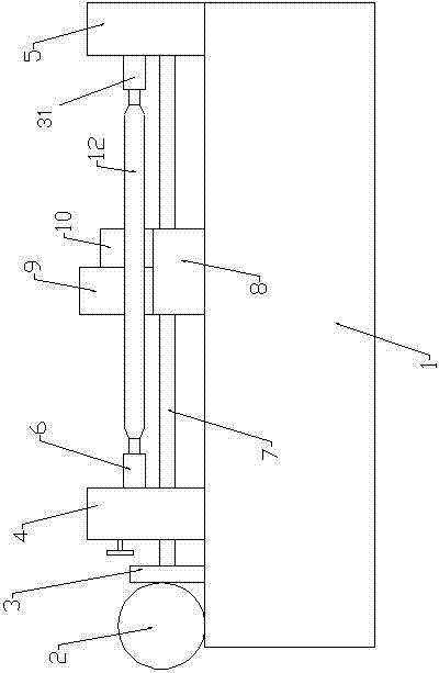
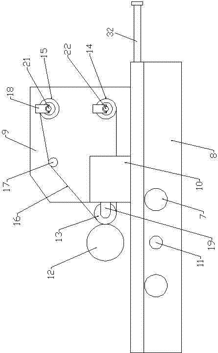
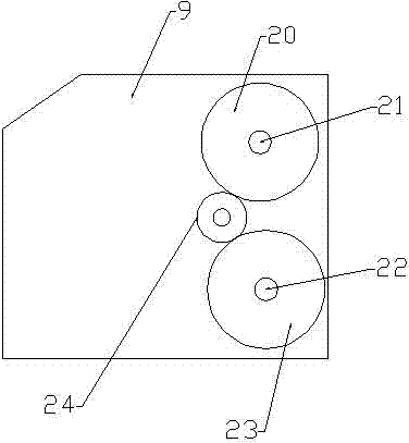
[0017] Such as figure 1 , 2 , 3, 4, and 5, a belt polishing machine includes a base 1, a propulsion motor 2 installed on the base 1, a first stroke support 3 and a second stroke support 5 arranged on one side of the propulsion motor 2, The guide rod 7 that is installed between the first stroke bracket 3 and the second stroke bracket 5 and the stroke propelling screw 11, the roller movable bracket 4 that is sleeved on the guide rod 7 and the stroke propelling screw 11 outside, and the roller movable bracket 4 The connected roller rotation drive shaft 6, the roller rotation driven shaft 31 installed on the top of the second stroke bracket 5, the polishing machine base 8 installed between the roller movable bracket 4 and the second stroke bracket 5, the described The polishing machine base 8 is sleeved on the outside of the guide rod 7 and the stroke propelling screw 11, a polishing transmission housing 9 and a polishing output housing 10 are arranged above the polishing mac...


PUM


Abstract

The invention relates to a strip-shaped polishing machine. A polishing machine base is arranged on the outer portion of a guiding rod and the outer portion of a stroke pushing screw rod in a sleeved mode. A polishing transmission shell body and a polishing output shell body are arranged above the polishing machine base. A polishing strip driven shaft and a polishing strip driving shaft with a motor are arranged on the polishing transmission shell body. A polishing wheel is arranged on the polishing output shell body. A first polishing strip rolling shaft is arranged on the polishing strip driving shaft. A second polishing strip rolling shaft is arranged on the polishing strip driven shaft. The polishing wheel, the first polishing strip rolling shaft and the second polishing strip rolling shaft are connected with polishing abrasive belts. The axis of the polishing wheel and the axis of a rolling shaft rotating driving shaft are parallel. Polishing quality is guaranteed, constant-speed taking up of the polishing abrasive belts during operation is achieved, the polishing performance of the contacting face of a rolling shaft is great, polishing accuracy is greatly improved, polishing speed and efficiency are improved, secondary using of the rolling shaft can be guaranteed each time polishing is carried out, expenditure is saved for an enterprise, benefit is brought, energy is saved, and environment is protected.

Description

technical field [0001] The invention relates to a polishing machine, in particular to a strip polishing machine. Background technique [0002] After the steel rolling roller is used many times, uneven pits will appear on the surface of the roller, which will affect the flatness of the pressed steel plate surface during use. If the roller is replaced, the cost will be high, resulting in a waste of resources. The traditional method is to polish the rolling roller on a professional polishing machine and then reuse it. During the polishing process, the uneven pits on the surface of the roller can be repaired and leveled, which will not affect the reuse. [0003] However, the current traditional roller polishing machine has certain defects in use: the polishing object used on the polishing machine is a polishing wheel, and the polishing wheel is used to move left and right on the roller, while the roller rotates to achieve the purpose of polishing. However, due to the current Th...

Claims


Application Information

Patent Timeline
Patent Type & Authority Applications(China)
IPC IPC(8): B24B21/02
CPCB24B21/02B24B21/18
Inventor 侯东欣
Owner HENAN XUYUAN STAINLESS STEEL
Learn More