
Efficient template fixture for accurately grinding guide bars

A technology of relying on molds and guide bars, which is applied in the field of tooling and fixtures, can solve the problems of low efficiency, high labor cost and high cost, and achieve the effect of reducing costs and improving efficiency.

Inactive Publication Date: 2014-03-05
宁波建欣精密模具有限公司
View PDF5 Cites 2 Cited by
  • Summary
  • Abstract
  • Description
  • Claims
  • Application Information

AI Technical Summary

Problems solved by technology

[0002] The automatic motor production line is equipped with an automatic wire inserting machine. The guide bar is an important part that carries and guides the coil winding on the automatic wire inserting machine, and embeds the coil winding into the stator slot; the guide bar is a consumable product that needs to be updated frequently, and requires high precision. The consumption is large; the grinding machine is required in the manufacture of the guide bar, especially the guide groove on the guide bar needs to be finely ground. Because the shape of the guide bar is slender and complicated, the existing technology adopts one piece The ground precision grinding process has extremely low efficiency and high man-hour cost. Therefore, the existing technology has the problems and deficiencies of low efficiency and high cost

Method used


Image

  • Efficient template fixture for accurately grinding guide bars
  • Efficient template fixture for accurately grinding guide bars
  • Efficient template fixture for accurately grinding guide bars

Examples


Embodiment Construction

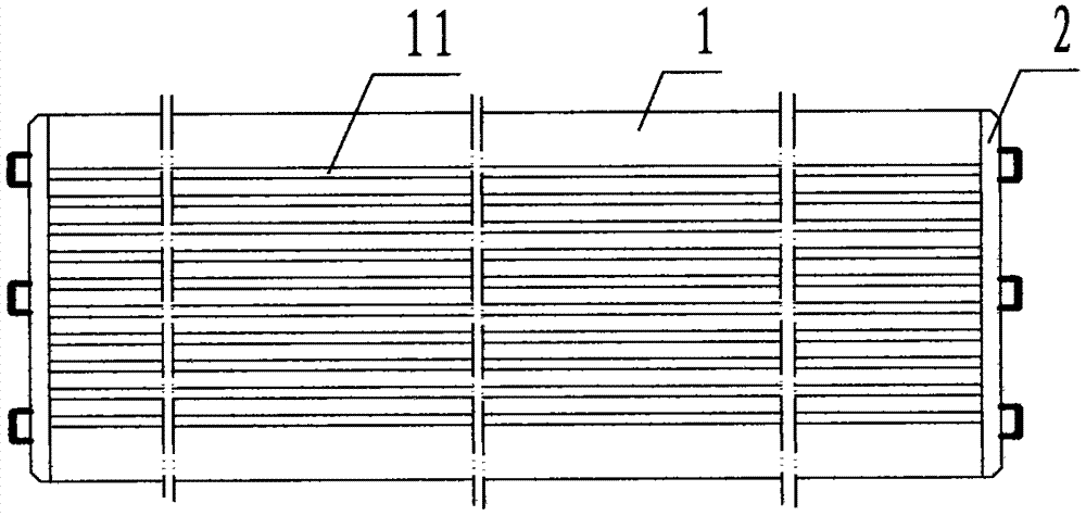
[0025] see Figure 1 to Figure 11 , the present invention: a high-efficiency mold jig for fine grinding guide bars, including a mold 1 and an end clamp plate 2, wherein: the mold 1 is a rectangular block-shaped steel plate, and the top of the mold 1 is provided with several strips The grooves in the left-right direction and parallel to each other are called the cavity groove 11, and the cross-sectional shape of the cavity groove 11 corresponds to the front and rear sides and the bottom of the cross-sectional shape of the guide bar workpiece 04;

[0026] Described end plate 2 is a rectangular block-shaped steel plate;

[0027] The end clamp plate 2 is connected to the left and right ends of the template 1 through screws.

[0028] The directional plane of the structural representation is divided into upper, lower, left, right, front and rear, wherein, the front is the plane facing the main body of the device, and the rear is the plane opposite to the front.

[0029] Working pr...


PUM


Abstract

The invention discloses an efficient template fixture for accurately grinding guide bars. The efficient template fixture comprises a template (1) and end clamp plates (2). The technical scheme includes that the device comprises the template and the end clamp plates, the template is a rectangular block-shaped steel plate, a plurality of parallel cavity grooves are formed in the template in the left-right directions, and the end clamp plates are arranged at the left end and the right end of the template; a group of guide bar workpieces is inlaid in each cavity groove of the template during application, and each group of guide bar workpieces comprises three guide bar workpieces which are connected with one another in an end-to-end manner and are provided with upward guide grooves; the template is positioned by the aid of angular positioning blocks and is sucked by a magnetic workbench; during operation, the three guide bar workpieces in one cavity groove can be completely ground whenever the workbench of a grinding machine reciprocates once, accordingly, the guide bar workpieces in the various cavity grooves can be accurately ground one by one until all the guide bar workpieces are completely accurately ground, and then a new template provided with guide bar workpieces replaces the template, so that the guide bar workpieces of the new template can be accurately ground. The efficient template fixture has the advantages that shortcomings of low efficiency and high cost in the prior art can be overcome, and purposes of improving guide bar product production efficiency and reducing guide bar product production cost can be achieved.

Description

technical field [0001] The invention relates to a tooling fixture, in particular to a high-efficiency die-backing fixture for fine-grinding guide bars used for precision-grinding guide-bar guide grooves. Background technique [0002] The automatic production line of the motor is equipped with an automatic wire embedding machine. The guide bar is an important component that carries and guides the coil winding on the automatic wire embedding machine, and embeds the coil winding into the stator slot; the guide bar is a consumable item that needs to be updated frequently and requires high precision. The consumption is large; the grinding machine needs to be used for grinding in the production and manufacture of the guide bar, especially the guide groove on the guide bar needs to be precisely ground. The precision grinding process has extremely low efficiency and high labor-hour cost. Therefore, the existing technology has problems and shortcomings of low efficiency and high cost...

Claims


Application Information

Patent Timeline
IPC IPC(8): B24B41/06B24B19/02
CPCB24B19/02B24B41/06
Inventor 谢梅邬建兵胡建东
Owner 宁波建欣精密模具有限公司
Learn More