Flywheel-driven carrying robot

A technology of robots and inertia wheels, applied in manipulators, program-controlled manipulators, manufacturing tools, etc., can solve problems such as different dynamic characteristics, high precision requirements, and difficulty in improving motion control accuracy

Inactive Publication Date: 2014-03-05
BEIJING JIAOTONG UNIV
View PDF5 Cites 4 Cited by
  • Summary
  • Abstract
  • Description
  • Claims
  • Application Information

AI Technical Summary

Problems solved by technology

Usually, the loading platform set on the robot realizes multi-degree-of-freedom attitude adjustment through the cascading of multi-level single-degree-of-freedom movable mechanisms. In the process of calculating the control quantity, multiple coordinate transformations are required, and the calculation is complicated; the error of the front-level mechanism will significantly affect the attitude adjustment accuracy of the last-stage loading platform after being amplified step by step, making it difficult to improve the accuracy of motion control; The dynamic characteristics of the mechanisms at all levels are different, so the characteristics of the loading platform on the robot are also different in each degree of freedom.

Method used


Image

  • Flywheel-driven carrying robot
  • Flywheel-driven carrying robot
  • Flywheel-driven carrying robot

Examples


Embodiment 1

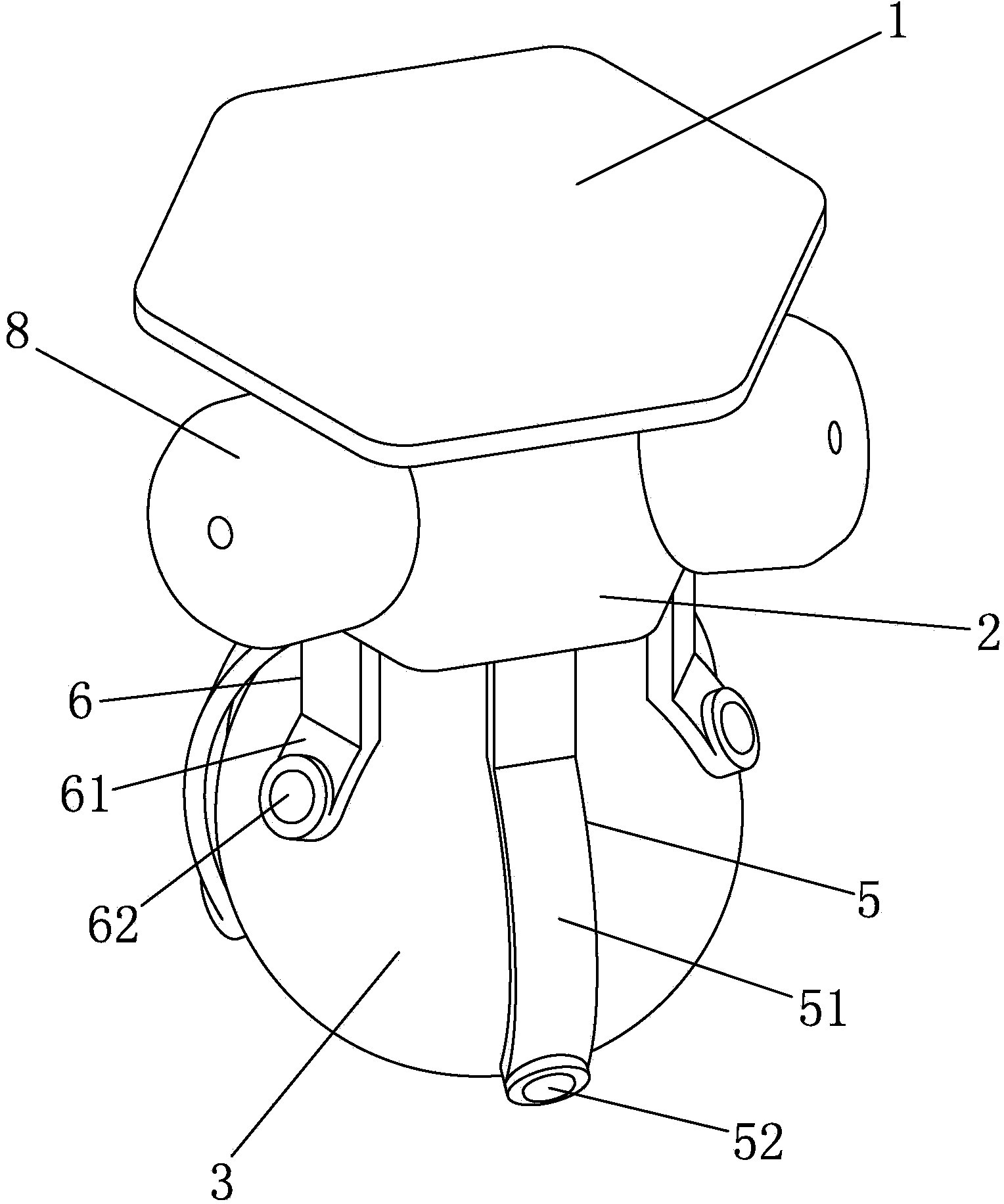
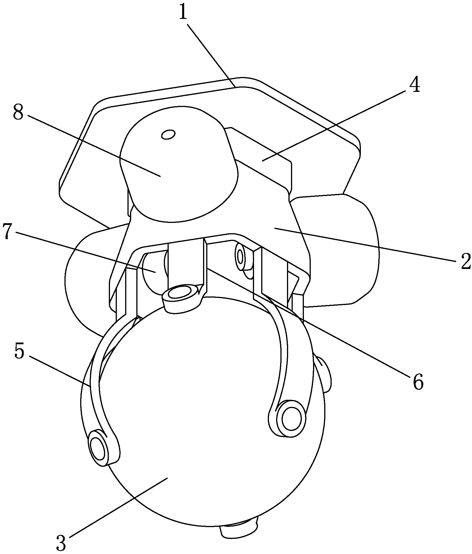
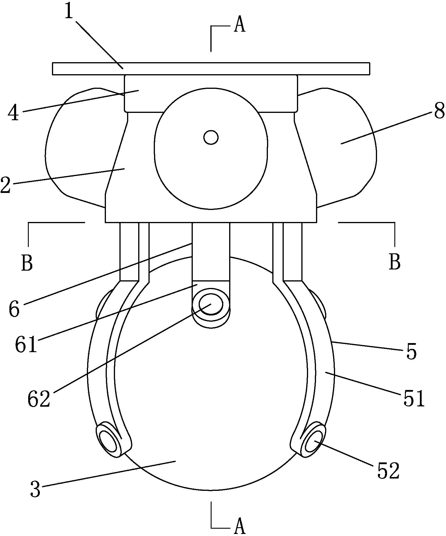
[0082] Such as Figures 1 to 7 As shown, a load-carrying robot driven by an inertia wheel includes a load-carrying platform 1, a fixed frame 2, a sphere 3, a support frame and a main controller cabin 4; the load-carrying platform 1 passes through the The main controller compartment 4 is fixedly arranged on the top surface of the fixed frame 2; the fixed frame 2 is arranged above the surface of the sphere 3 through a support frame;

[0083] The inner space of the support frame constitutes a confinement chamber, the sphere 3 is rotatably arranged in the confinement chamber, and the lower end of the sphere 3 is exposed outside the confinement chamber; the bottom end of the sphere 3 is in contact with the ground, and the sphere 3 is Constrained in the confinement chamber, the sphere 3 itself can freely rotate in any direction and cannot move in translation.

[0084]Described support frame comprises three long support frames 5 and three short support frames 6; Fixed connection, t...

Embodiment 2

[0095] Such as Figures 8 to 11 As shown, the difference between this embodiment and Embodiment 1 is that the support frame includes three long support frames 5 and one short support frame 6; the three long support frames 5 are evenly arranged along the circumference of the fixed frame 2, and the three long support frames The frame body of the support frame 5 is provided with a first bending portion 51 matching the curvature of the surface of the sphere 3, and the first bending portion 51 is provided with a first universal ball 52, and the first universal ball The spherical surface of the ball 52 is in contact with the spherical surface of the lower half of the spherical body 3;

[0096] The upper end of the short support frame 6 is affixed to the fixed frame 2, and the lower end of the short support frame 6 is provided with a second universal ball 62, and the spherical surface of the second universal ball 62 is connected to the top of the sphere 3. contact with the surface o...

Embodiment 3

[0101] Such as Figures 12 to 15 As shown, the difference between this embodiment and Embodiment 1 or 2 is that the support frame includes three long support frames 5; the three long support frames 5 are evenly arranged along the circumference of the fixed frame, and the frames of the three long support frames 5 The body is provided with a first bending portion 51 matching the curvature of the surface of the sphere 3, and the first bending portion 51 is provided with a first universal ball 52, and the spherical surface of the first universal ball 52 is in line with the The surface of the lower half of the sphere 3 is in contact with the surface; the bottom surface of the fixed frame 2 is provided with a second universal ball 62 , and the spherical surface of the second universal ball 62 is in contact with the top surface of the sphere 3 .

[0102] The point where the first universal ball 52 on the long support frame 5 contacts with the sphere 3 and the central axis 9 of the lo...


PUM


Abstract

The invention discloses a flywheel-driven carrying robot comprising a carrying platform, a fixing frame, a ball and supporting frames. The carrying platform is fixedly arranged on the top face of the fixing frame which is arranged above the surface of the ball through the supporting frame, a constraint chamber is formed in an internal space of the supporting frames, the ball is rotatably arranged in the constraint chamber, the lower end of the ball is exposed out of the constraint chamber, three direct-current motors are arranged on the fixing frame uniformly and circumferentially, and a flywheel is fixedly arranged on an output shaft of each direct-current motor. The carrying platform has multi-degree-of-freedom adjustment capability in attitude, multi-degree-of-freedom movement can be realized only by a one-stage moving mechanism, movements of all degrees of freedom have no cascade relation, and the problem that error of a conventional carrying platform is amplified step by step is avoided; solving methods of the movements of all the degrees of freedom are identical, kinetic characteristics are also identical, and control is simplified.

Description

technical field [0001] The invention relates to an object-carrying robot, in particular to an object-carrying robot driven by an inertia wheel. Background technique [0002] In order to meet the needs in the field of industrial automation production, various robots with loading platforms have been invented and manufactured. With the development of mechanical processing and manufacturing technology, power electronics technology and automatic control technology, the shape and structure of robots have also become diversified, and these robots have intelligent control cores, which can realize single-point motion control accurately, stably and quickly. Various motion controls such as multi-point motion control or curve motion control. Usually, the loading platform set on the robot realizes multi-degree-of-freedom attitude adjustment through the cascading of multi-level single-degree-of-freedom movable mechanisms. In the process of calculating the control quantity, multiple coor...

Claims


Application Information

Patent Timeline
Patent Type & Authority Applications(China)
IPC IPC(8): B25J9/00
Inventor 董春马卓标王志群
Owner BEIJING JIAOTONG UNIV
Why Eureka
Try Eureka