

An energy-saving mechanism with double backup for U-shaped track and suspension drive for safe operation
A safe operation, suspension drive technology, applied in the field of rail transit, can solve the problems of small distance, low efficiency of driving linear motor, affecting the normal operation of rail transit, etc.
- Summary
- Abstract
- Description
- Claims
- Application Information
AI Technical Summary
Problems solved by technology
Method used
Image

Examples
Embodiment 1
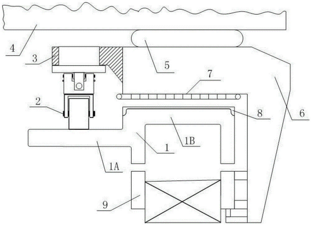
[0049] A kind of U-shaped track double backup safe operation and suspension drive energy-saving mechanism, such as figure 1 , figure 2 , image 3 with Figure 8 shown;
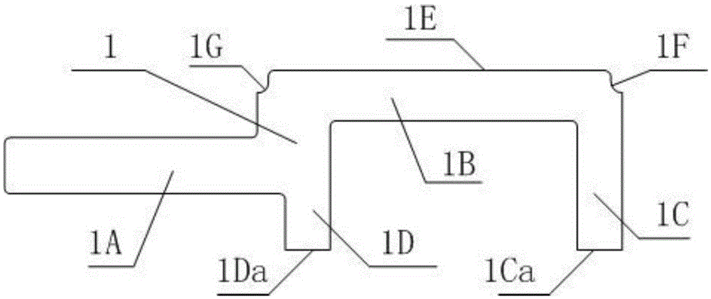
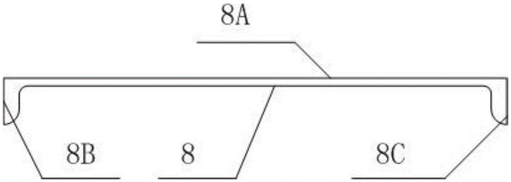
[0050] A U-shaped rail double-backup safe operation and suspension drive energy-saving mechanism is characterized in that it consists of a U-shaped track 1, a self-locking hydraulic travel wheel mechanism 2, a connecting frame 3, a car body 4, an air spring 5, a bogie arm 6, The spindle 7, the aluminum induction plate 8, and the levitation magnet 9 are composed. The U-shaped track 1 is installed on the sleeper or on the track beam; the aluminum induction plate 8 is installed on the outer surface of the groove bottom plate of the U-shaped track 1; Above, the bottom of the car body 4 is connected to the upper surface of the bogie arm 6 through the air spring 5, and the spindle 7 of the linear motor is installed on the lower surface of the bogie arm 6, and is completely corresponding to the aluminum inductio...
Embodiment 2
[0071] Other is with embodiment 1, and difference is:
[0072] The U-shaped track 1 is directly produced by a hot rolling process, and the corners of each part of the U-shaped track 1 are circular arcs with a radius of 1-5mm according to the requirements of the hot rolling process or performance requirements.
[0073] The distance between the upper surface of the U-shaped track installation wing plate 1A and the outer surface 1E of the groove bottom is 100 mm.
[0074] The walking wheel 2A of the double backup safe operation that is matched with U-shaped track is wear-resistant solid rubber wheel.
Embodiment 3
[0076] Other is with embodiment 1, and difference is:
[0077] The U-shaped track 1 is directly produced by a hot rolling process.
[0078] The distance between the upper surface of the mounting wing 1A and the outer surface 1E of the groove bottom is 40mm.
[0079] The walking wheel 2A of the double standby safe operation that is matched with U-shaped track is wear-resistant steel wheel.
PUM
 Abstract
Description
Claims
Application Information